


PG-FP5 V2.13 EXAMPLE OF OPERATION USING PROGRAMMING GUI
R20UT2924EJ0200 Rev.2.00 Page 57 of 71
Mar 02, 2015
2. EXAMPLE OF OPERATION USING PROGRAMMING GUI
This chapter explains a series of basic FP5 operations using the programming GUI, taking a case where the RH850/F1L
is used as the target device as an example. This chapter covers how to start the system, execute the
[Autoprocedure(E.P.)] command and program the target device.
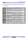
• Series of operations described in this chapter:
The operation conditions for this chapter are as follows.
Host PC interface: USB
Programming area: Divided by 2, Area 0
Target device: R7F701023 (RH850/F1L) (on evaluation board)
Supply oscillator: 24MHz
Communication interface to device: 2 wire UART @ 2Mbps
Security mode: Command protection mode
Operation area: All blocks
Command protection: Not used
The operation steps described in this chapter are as follows
(1) Installation of programming GUI and USB driver
(2) Installation of PR5 file
(3) System connection
(4) Connection of target system
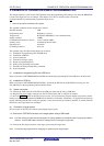
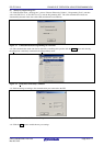
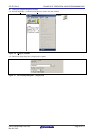
(5) Startup of programming GUI
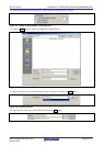
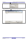
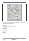
(6) Setting of programming environment
(7) Execution of [Autoprocedure(E.P.)] command
(8) System shutdown
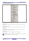
(1) Installation of programming GUI and USB driver
Refer to Common 3 SOFTWARE INSTALLATION and install the programming GUI and USB driver in the host PC.
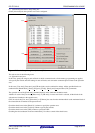
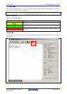
(2) Installation of PR5 file
Refer to Common 3 SOFTWARE INSTALLATION , download the PR5 file for the R7F701023 and copy it to the
FP5_PRJ folder in the programming GUI installation folder.
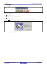
(3) System connection
<1> Connect the USB connector of the FP5 to the USB port on the host PC using a USB cable.
<2> Plug the FP5 power supply connector into the AC outlet (100 to 240 V) using the AC adaptor.
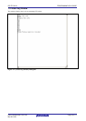
<3> Press the POWER button on the FP5 to turn on power. Do not connect the program adaptor (target device) before
turning on power. Confirm that the POWER LED on the FP5 is off and that ‘Commands >’ is displayed in the message
display, indicating that the FP5 is ready for operation. If not, the cause may be a defect in the FP5, so consult a Renesas
Electronics sales representative or distributor.
(4) Connection of target system
Be sure to turn on the FP5 power before connecting the target system.
<1> Connect the FP5 GND connector to the target system using a GND cable.
Note The FP5 and target system may be damaged if the voltage between the FP5 GND and the target system GND is
different. Use the GND cable to match the voltage before connecting the target cable.
<2> Connect the FP5 target connector to the target system using the target cable.
Note Connect the target system before supplying VDD power from the target system.