


PG-FP5 V2.13 PROGRAMMING GUI USAGE
R20UT2924EJ0200 Rev.2.00 Page 44 of 71
Mar 02, 2015
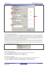
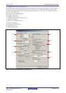
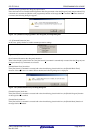
[CPU Frequency] box
Displays the maximum oscillation frequency of the clock set for the target device. Placing a check mark in the [Edit
CPU Frequency] box allows you to change the frequency.
Note For the specifiable CPU frequency, refer to the user’s manual of the target device.
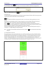
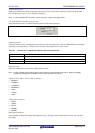
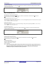
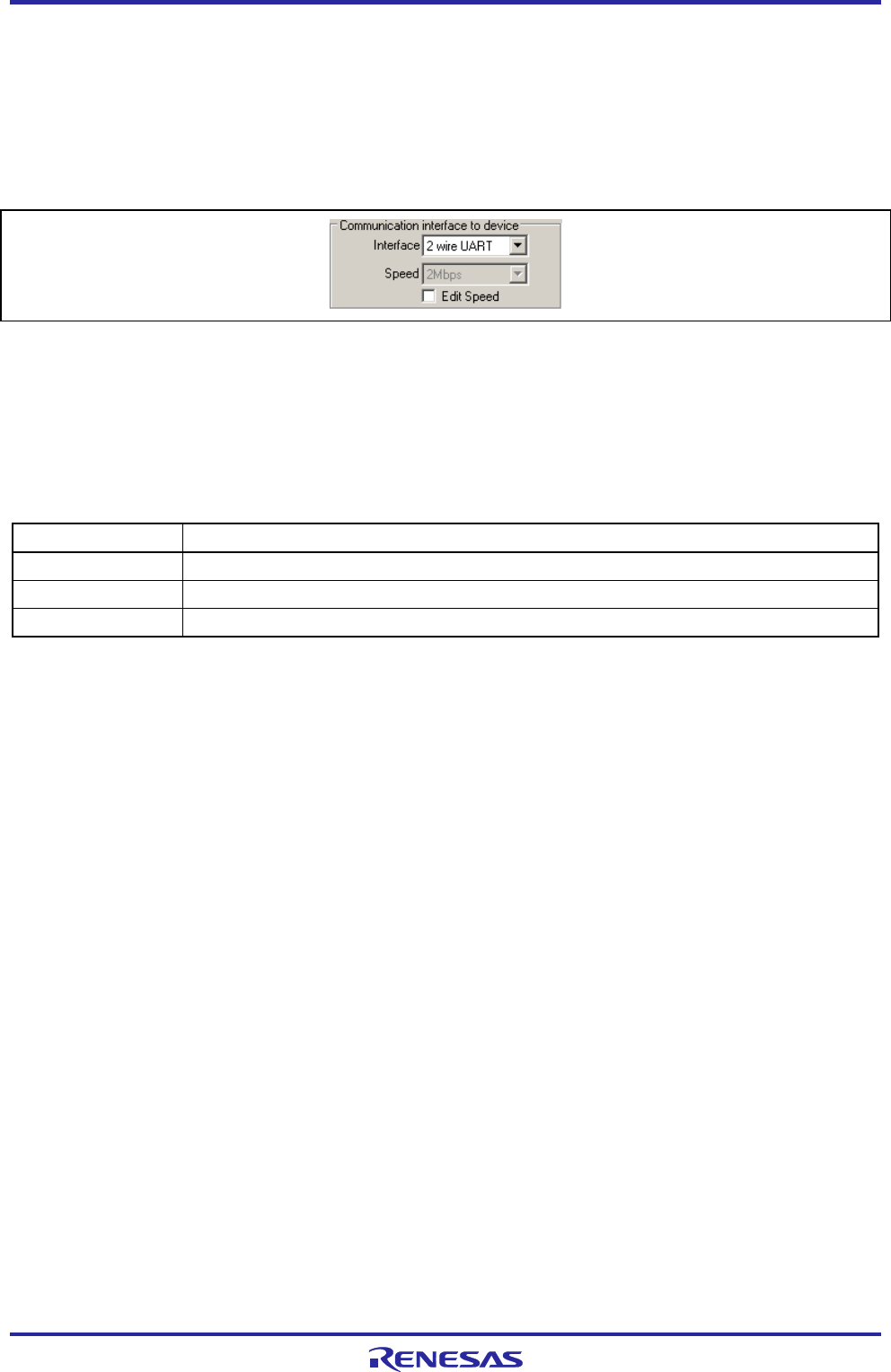
<3> [Communication interface to device] area
Select the interface mode of communications between the FP5 and target device.
Figure 1.62 [Communication interface to device] Area
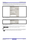
[Interface] list box
Select the interface mode of communications between the FP5 and target device. The specifiable interface mode differs
depending on the target device. Check the user’s manual of the target device to select a mode.
Table 1.3 Channels for Communication Between FP5 and Target Device
Item on Screen Description
1 wire UART
1 wire UART (asynchronous communication interface)
2 wire UART 2 wire UART (asynchronous communication interface)
CSI 3 wire CSI (clocke communication interface)
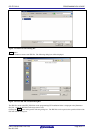
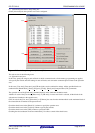
[Speed] List box
Select the communication speed of the selected interface mode.
Note For the available communication speed, refer to the user’s manual of the target device. Setting the [Supply
oscillator] area displays the selectable communication speeds in the list box.
< When 1 wire UART or 2 wire UART is selected >
• 9600Baud
• 38400Baud
• 115200Baud
• 500000Baud
• 1Mbps
• 1.5Mbps
• 2Mbps
< When CSI is selected >
• 9.8kHz
• 156kHz
• 625kHz
• 2500kHz
• 5000kHz
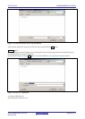
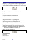
[Edit Speed] check box
Select whether to change the settings in the [Speed] List box. Placing a check mark in this box allows you to change
the settings.