


PG-FP5 V2.13 PROGRAMMING GUI USAGE
R20UT2924EJ0200 Rev.2.00 Page 26 of 71
Mar 02, 2015
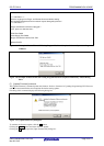
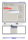
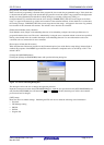
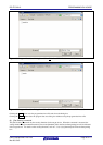
• FP5 Manager Dialog Settings (Refer to Figure 1.34)
[Disable Upload] check box
This sets enabling or disabling of the upload function used to upload data (program file, PR5 file, ESF file) from the
valid programming area of FP5 to the host PC. Checking the box will disable and unchecking it will enable the
function. When this function is disabled, the [File] menu -> [Upload from FP5...] command, and the hex, srec, and
upset of the communications command are disabled. The default is not to have this box checked.
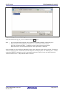
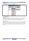
[Disable Device Setup] check box
Enables or disables the [Setup] command in the [Device] menu. It is disabled when checked, and enabled when not
checked. When it is disabled, the [Setup] command in the [Device] menu, as well as the downprm, downset, and lod
communication commands become invalid.
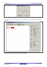
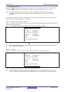
[Enable Bank mode] check box
Sets the normal mode or bank mode for the mode of the remote connector. Checking this box will set the bank mode,
and not checking it will set the normal mode. If checked, [Enable Simple mode] cannot be checked. When in the bank
mode, the programming area can be selected through the remote connector. With respect to detailed functions, refer to
Common 5 USAGE THE REMOTE CONNECTOR. The default is not to have this box checked.
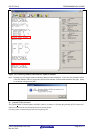
[Enable Simple mode] check box
Sets the normal mode or the simple mode. Checking this box will set the simple mode, and not checking it will set the
normal mode. If checked, [Enable Bank mode] cannot be checked. When in the simple mode, the functions of the FP5
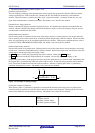
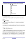
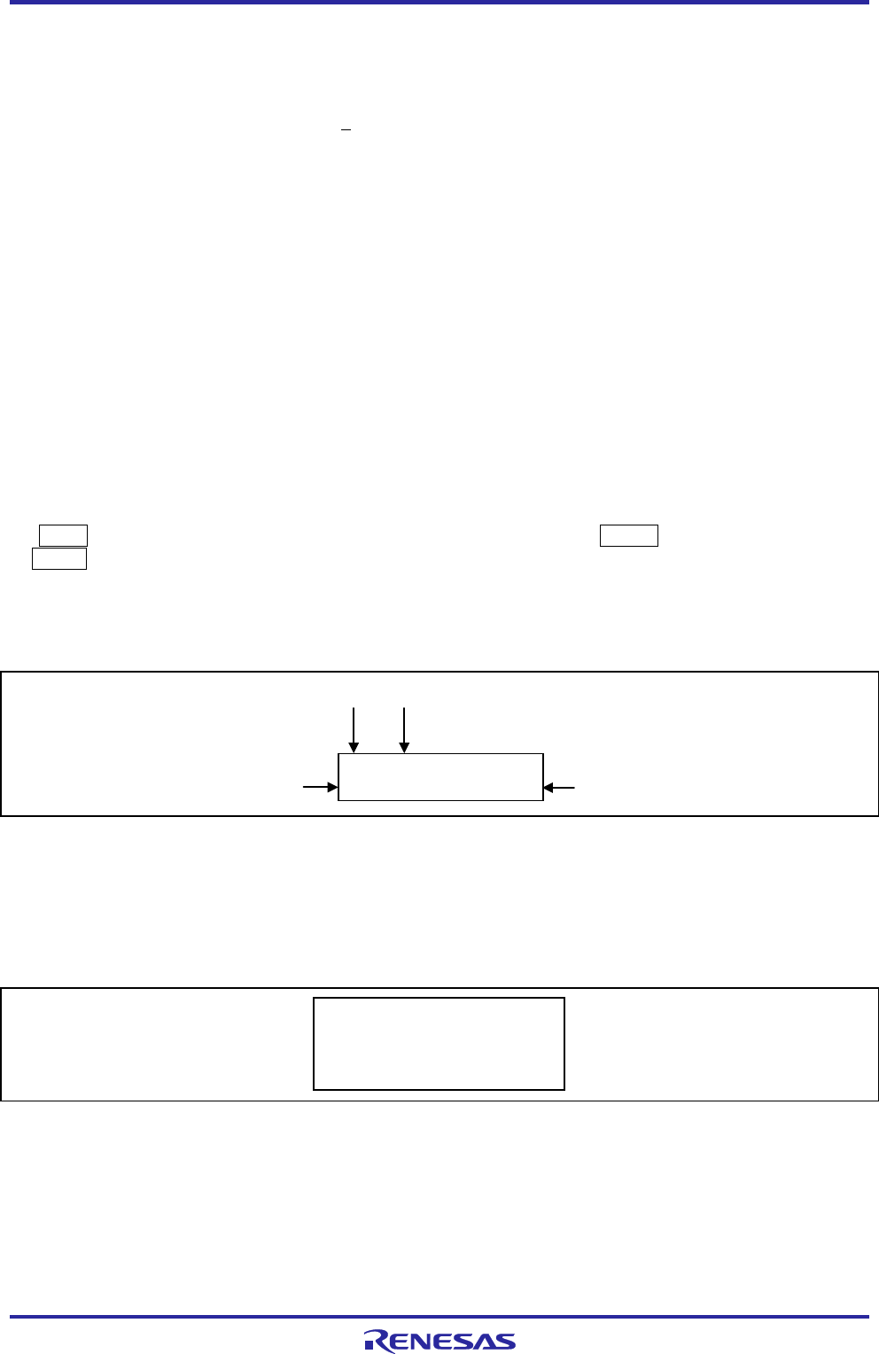
control buttons and message display will change. When
the NEXT button is clicked, the programming area will be switched. Clicking the ENTER button
or START button will execute the Autoprocedure(E.P.) command. The message display will display (1) the
programming area number, (2) the program file name, and (3) the checksum and (4) command name. Immediately after
the program file is downloaded, the checksum will show H:xxxxxxxx. At this time, the program file will be checked
using 32-bit CRC calculations from the start to the end address. After this, executing [File] menu -> [Checksum]
command will display F:xxxxxxxx. The default is not to have this box checked.
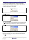
0:sample.hex
H:AFE33BC0 E.P.>
(1)
(2)
(3)
(4)
Figure 1.35 Example of Message Display
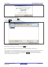
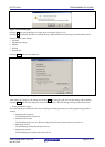
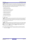
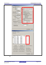
[Checksum comparison] check box
When [Device] menu -> [Checksum] command is executed and the checksum of the target device is displayed, the
checksum of the program file stored in FP5 will be referenced and the results displayed. Checking this box will cross-
reference the checksum, and not checking it will not. The default is not to have this box checked.
>Sum
Checksum: 0x623E
Checksum compare: PASS
Checksum operation: finished.
Figure 1.36 Example of Action Log Window