PG-FP5 V2.13 PROGRAMMING GUI USAGE
R20UT2924EJ0200 Rev.2.00 Page 51 of 71
Mar 02, 2015
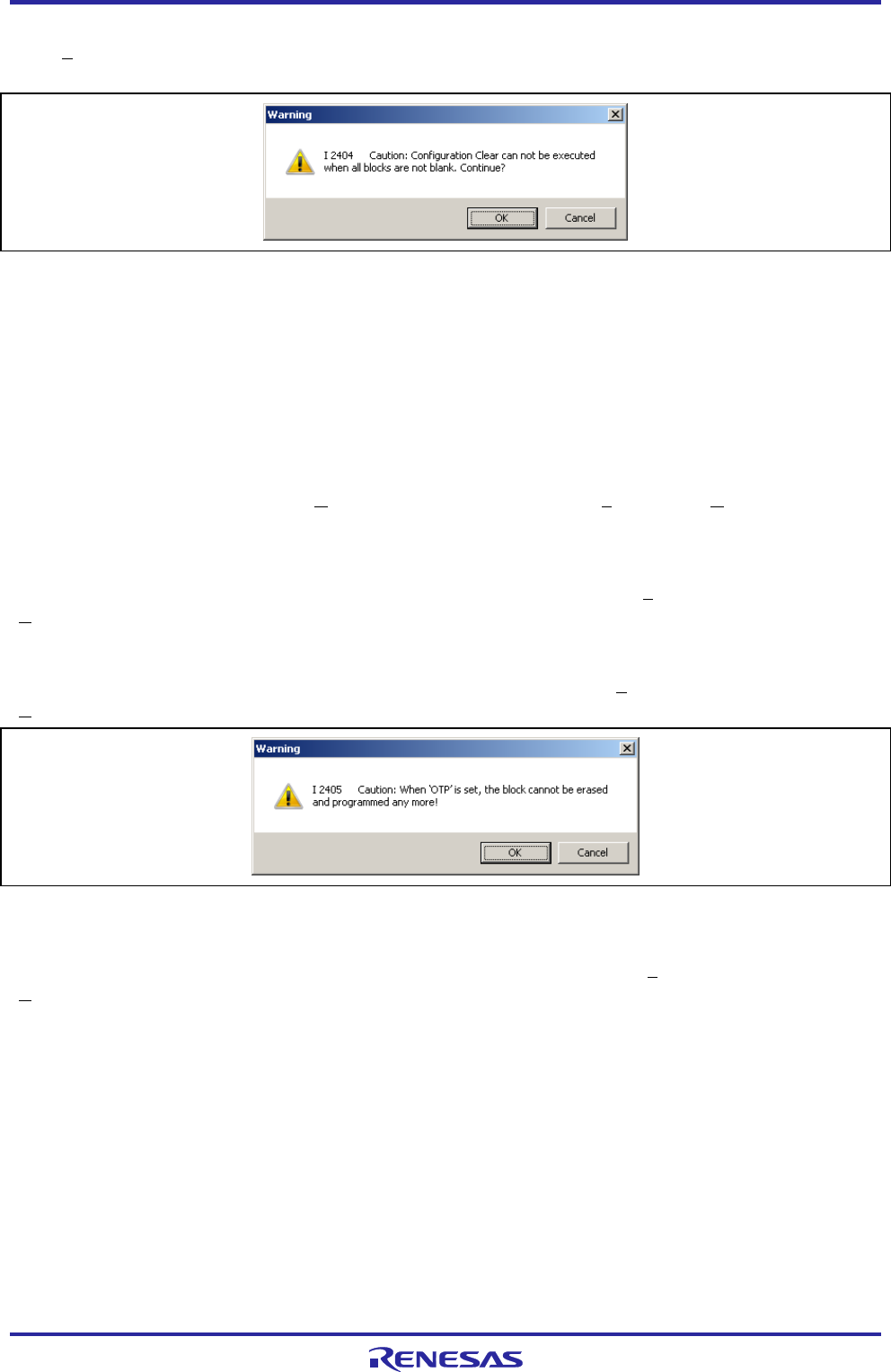
[Configuration Clear after Erase] check box
If the [Erase] command is executed with this check box checked, the [Configuration Clear] command of the target
device is executed. When checked, the following dialog box is displayed.
Figure 1.73 [Configuration Clear after Erase] Warning Dialog Box
[Enable minimum unit programming] check box
This is a function for programming of the data flash memory in the minimum unit. Placing a check mark in this box
enables the function. Once enabled, writing to, verifying, and reading from the data area in the data flash memory in the
minimum unit of the MCU’s flash memory control are possible. This function can be used when the RH850 (Except
RH850/F1L) is selected.
[Verify after Program] check box
If a check mark is placed in this box, the [Verify] command is executed after the [Program] and [Autoprocedure(E.P.)]
commands are executed.
[Set Lock bit after Program] check box
If a check mark is placed in this box, the [Set Lock bit] command is executed after the [Program] and
[Autoprocedure(E.P.)] command is executed.
[Set OTP after Program] check box
If a check mark is placed in this box, the [Set OTP] command is executed after the [Program] and
[Autoprocedure(E.P.)] commands are executed. When checked, the following dialog box is displayed.
Figure 1.74 [Set OTP after Program] Warning Dialog Box
[ICU validate after Program] check box
If a check mark is placed in this box, the [ICU validate] command is executed after the [Program] and
[Autoprocedure(E.P.)] commands are executed. When the microcontroller without the ICU function is selected, this
check box is hdden.
Note For the configuration clear, lock bit, OTP, and ICU, refer to the user’s manual of the target device.


