


PG-FP5 V2.13 PROGRAMMING GUI USAGE
R20UT2924EJ0200 Rev.2.00 Page 43 of 71
Mar 02, 2015
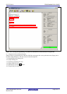
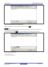
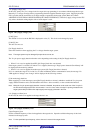
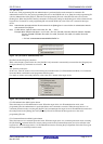
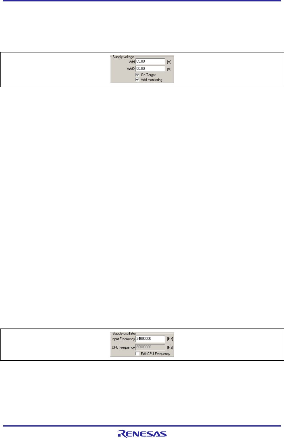
<1> [Supply voltage] area
In this area, specify one (V
DD) voltage levels for target device programming, in accordance with the target device type.
Basically, V
DD voltages for target device programming should be supplied from the target system. Supplying from the
FP5 is possible, but the current flow is not large enough to operate the whole target system (Refer to Common
APPENDIX C ELECTRICAL SPECIFICATIONS OF TARGET INTERFACE). Therefore, supply voltage via the FP5
only when a dedicated writing adaptor such as an FA adaptor is used.
Figure 1.60 [Supply voltage] Area
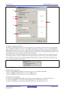
[Vdd[V]] box
The default V
DD level set in the PR5 file is displayed in volts (V). This level can be changed by input.
[Vdd2[V]] box
This box does not use.
[On Target] check box
Select this check box when supplying the V
DD voltages from the target system.
Note The target system may be damaged if proper values are not set.
The V
DD pin power supply detection function varies depending on the setting of the [On Target] check box.
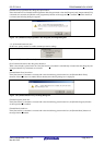
• When VDD is set to be supplied from FP5 ([On Target] check box: not selected)
If the target system V
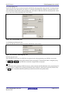
DD exceeds 0.2V before VDD is supplied, the message “Target power detected! Check Setup” will
be displayed in the action log window.
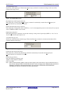
• When VDD is set to be supplied from the target system ([On Target] check box: selected)
If V
DD is outside the range of ±5% of the VDD set value immediately before communication starts, the message “No
VDD applied or Voltage is out of range” will be displayed in the action log window.
[Vdd monitoring] check box
When supplying V
DD from the target system ([On Target] check box: selected), whether to enable the VDD pin power
supply detection function can be selected with this check box. Select to enable, or clear to disable the function.
Note When the VDD pin power supply detection function is disabled, the product can be used even if the VDD pins in
the FP5 and the target system are not connected. In such a case, make sure that V
DD power generated in the
target system always matches the output signal power supply generated in the FP5.
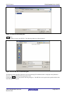
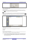
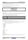
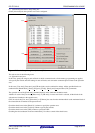
<2> [Supply oscillator] area
In this area, the clock to be supplied to the target device is set.
Figure 1.61 [Supply oscillator] Area
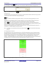
[Input Frequency] box
Set the oscillation frequency of the clock supplied to the target device. Input the oscillation frequency of the clock
mounted on the target system.
Note For the specifiable input frequency, refer to the user’s manual of the target device.