


15 (GB)
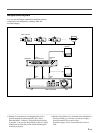
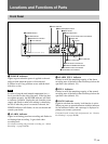
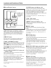
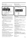
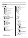
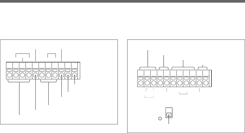
9 Alarm terminals
For input and output of various alarm and timing
signals. The COM terminals are all for ground.
ALARM terminals
For signals that can be triggered for alarm recording
IN: Alarm signal input (normally-open contact)
RESET: Alarm reset input (normally-open contact)
OUT: Sensor alarm signal output (5V DC/5.7 kΩ).
The output level drops to 0 V when the built-in
activity detection sensor operates or an external
alarm is detected.
NON REC OUT terminal (5V DC/5.7 kΩ)
The output level drops to 0 V if recording is
interrupted.
CLOCK terminals
You may adjust the built-in clock using an external
switch or synchronize the clocks of other connected
devices to the clock of this unit.
IN: Clock input (normally-open contact). Connect an
external switch or equivalent.
OUT: Clock output (5V DC/5.7 kΩ). The output level
drops to 0 V at the time you specified by menu
operation.
WARNING OUT terminal (5V DC/5.7 kΩ)
The output level drops to 0 V if any problem occurs
with the HDD or fan.
FULL terminal (5V DC/5.7 kΩ)
The output level drops to 0 V if the remaining capacity
of the normal recording area of the built-in hard disk
drops below the specified value (default: 1%).
ALARM FULL terminal (5V DC/5.7 kΩ)
The output level drops to 0 V if the remaining capacity
of the alarm recording area of the built-in hard disk
drops below the specified value (default: 1%).
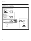
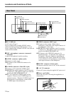
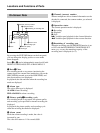
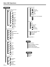
0 Control terminals
For input and output of various control signals. The
COM terminals are for ground.
RS485 terminals
For an RS-485 interface. Connect to the A, B, and
COM (ground) pins of a controller using a twisted-pair
cable.
For the connections, see “Remote Control Connections and
Associated Settings” on page 41(GB).
REMOTE terminals (resistor-alley system)
For remote control.
For the connections, see “Remote Control Connections and
Associated Settings” on page 41(GB).
SERIES terminals
To connect the control signal in series when
connecting video and audio signals for multiple HSR-
X200/X200P units in series.
IN: Connect to the OUT terminal of the previous
HSR-X200/X200P unit.
OUT: Connect to the IN terminal of the next HSR-
X200/X200P unit.
SW OUT terminals (5V DC/5.7 kΩ)
For pulse signal output. By connecting to SW of a
multiplexer, you may control the timing to switch the
input picture.
RS485 TERMINATE switch
For RS-485 termination. When connecting multiple
HSR-X200/X200P units in series via the RS485
terminals, set this switch of the last HSR-X200/X200P
unit to ON.
qa All Reset button
For CPU reset
IN INOUT OUT
WARNING OUT
CLOCK
NON REC OUT
ALARM
RESET
FULL
ALARM
FULL
COMCOM
ALARM terminals
NON REC OUT terminal
CLOCK terminals
WARNING OUT terminal
FULL terminal
ALARM FULL terminal
ON
RS485
TERMINATE
OFF
AB
IN OUTCOM COMCOMCOM COM
REMOTE
RS485
SERIES
SW OUT
RS485 TERMINATE switch
RS485 terminals
REMOTE terminal
SERIES terminals
SW OUT terminal