


Physical Description AXIS 2100 User’s Guide
8
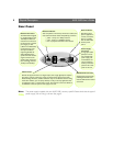
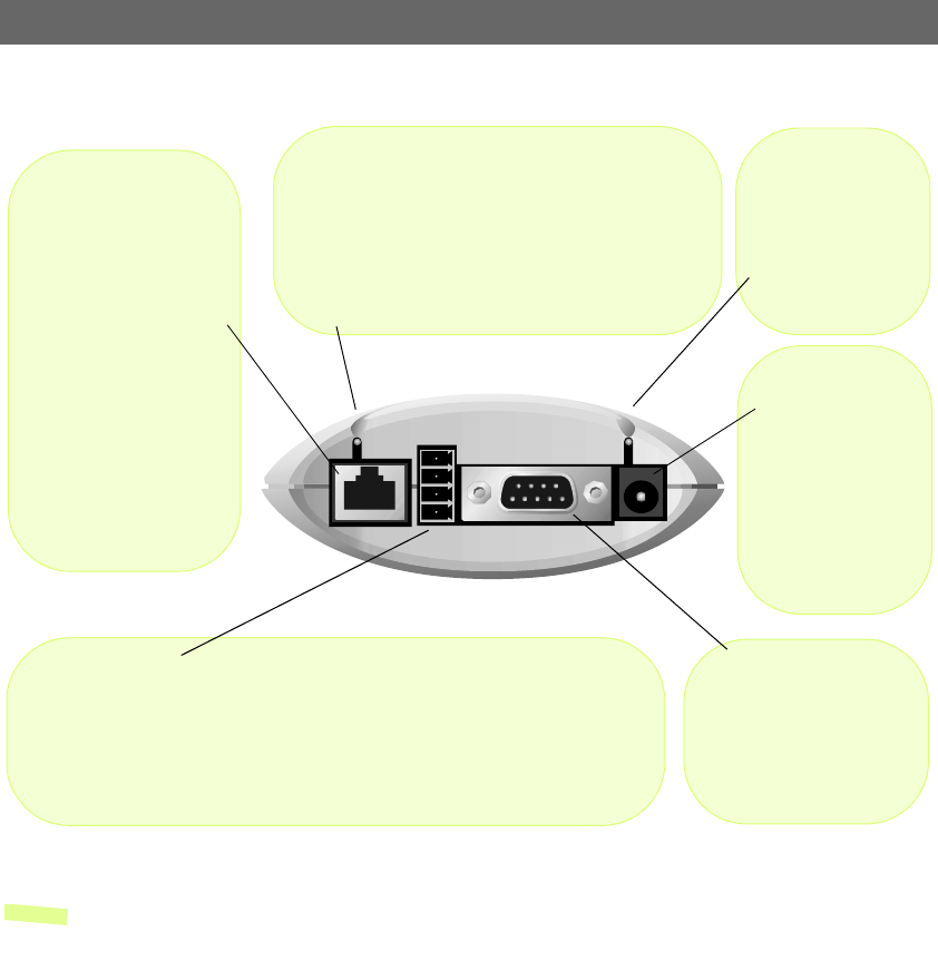
Rear Panel
Note: The power supply supplied with your AXIS 2100 is country specific. Please check that the type of
power supply you are using is correct. See page 9.
Power Supply
Connector
A single Jack socket
(PS-D) for connec-
tion of AXIS 2100
power supply. The
terminal block con-
nector provides an
auxiliary connection
point for AC or DC
power to the unit.
Power Indicator
Normally lit when
power is applied. If it
is not lit, or it flashes,
there is a problem
with the AXIS 2100
external power
source.
Network Indicator
After completion of the startup and self test routines, this
multi-colored indicator flashes independently, as follows:
• yellow - activity on a 10Mbps network
• green - activity on a 100Mbps network
• red - no physical connection to the network
Network Connector
The AXIS 2100 is designed
for 10 Mbps Ethernet and
100 Mbps Fast Ethernet
networks and connects to
the network via a twisted
pair category 5 cable
(10baseT and 100baseTX)
terminated using a stan-
dard RJ-45 connector.
Supporting NWAY, the
AXIS 2100 detects the
speed of the local network
segment and varies the
speed of data communica-
tion accordingly, between
10 Mbps and 100 Mbps.
I/O Connector
Provides the physical interface to a digital output, and a single digital photo-coupled
input that is used for connecting a variety of external alarm devices to the AXIS
2100; including, IR-sensors, switches and alarm relays. In combination with the config-
urable alarm facilities, you can quickly develop a variety of security applications that
are triggered on time - or alarm based - events. The connector can also be utilized as
an alternative connection point for DC supply to the unit.
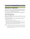
RS-232 Serial Connector
Single 9-pin D-sub connector
providing the RS-232 serial
interface dedicated for modem
connection.