


AXIS 2100 User’s Guide The Unit Connectors
47
Appendix C - The Unit Connectors
This section provides a detailed overview of the two supported product connectors: the Serial
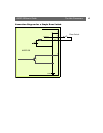
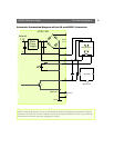
Connector and the IO Connector. It also includes connection diagrams for simple door switch and
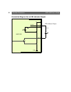
an LED output, as well as a more complete schematic diagram describing how the AXIS 2100 is
connected for a typical application.
The Serial Connector
In the absence of a local network connection, the RS232 serial connector provides a physical
interface for connecting a modem or computer to the AXIS 2100. This means that the AXIS 2100
can operate as a standalone unit - independent of any computer network. When a local network
connection is unavailable at the point of installation, connect your PC to this connector using the
supplied Null Modem Cable to initially configure your product.
The Physical Connector
A single 9 pin D-sub connector provides the physical connection for the RS232 serial interface of
the AXIS 2100. This connector is dedicated for use with an external modem and is suitable for
speeds up to 115kbps.
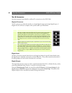
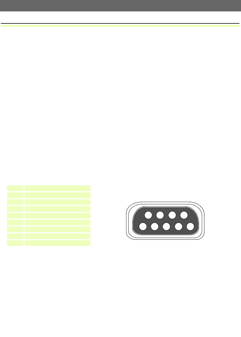
A diagram of the RS232 connector’s pinout information is shown below.
Pin Function
1 CD (Carrier Detect)
A view of the RS232 Serial Port from the rear of the AXIS 2100
2 RXD (Receive Data)
3 TXD (Transmit Data)
4 DTR (Data Terminal Ready)
5 GND (Ground)
6 DSR (Data Signal Ready)
7 RTS (Return To Send)
8 CTS (Clear To Send)
9 RI (Ring Indicator)
987
6
5432
1