


The Unit Connectors AXIS 2100 User’s Guide
48
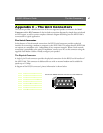
The IO Connector
A 4-pole connector is provided for auxiliary IO connections to the AXIS 2100.
Physical Connector
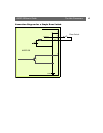
The IO connector provides the interface to a single digital output and a single digital input. A
diagram for the connector complete with a pinout table is provided below.
Digital Input
Used for connecting external alarm devices and triggering images for specific alarm-based events,
the digital input is typically connected to a motion detector - or any other external security device -
for taking images on each occasion the detector is activated.
Digital Output
The supported transistor output can drive a maximum load of 24V DC at 100mA directly, and by
connecting additional relay circuitry, it can drive even heavier loads.
Using the Administration Tools, you must first enable IO Status in the Layout Settings for the
Digital Output ON/OFF buttons to be displayed in the product Home Page. The status of the
Digital Output is then controlled by simply clicking these buttons.
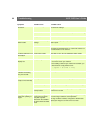
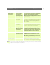
Pin Function
1 Common Ground
2 Positive Connection for DC Power Input or Output:
Electrically in parallel with the derived DC power for the unit, this pin may be used as a
power input or output. As a power input it can be used for remote applications to
supply the AXIS 2100 via an external direct current source; for example, a 9-15V DC
battery supply. Used as a power output, it can drive the photo coupled input or other
equipment; such as an infrared sensor. The output voltage level is dependent upon the
input voltage to the unit. A maximum current of 50mA can be sourced from the DC
output.
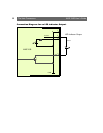
3 Digital Input (photo-coupled anode on the diode):
Voltages 5-24V DC will activate the input. It is possible to use pin 2 to source the input.
4 Digital Transistor Output:
With a maximum load of 100mA and a maximum voltage of 24V DC, this output has an
open-collector NPN transistor with the emitter connected to pin 1. If it is to be used
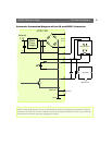
with an external relay, a diode must be connected in parallel with the load for protection
against any voltage transients - as detailed in the Schematic Connection Diagram of the I/O
and RS232 Connector, on page 51. Note: Connecting AC to the transistor output will
damage the unit.
1
2
3
4