


AXIS 2100 User’s Guide The Unit Connectors
51
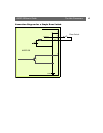
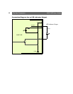
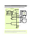
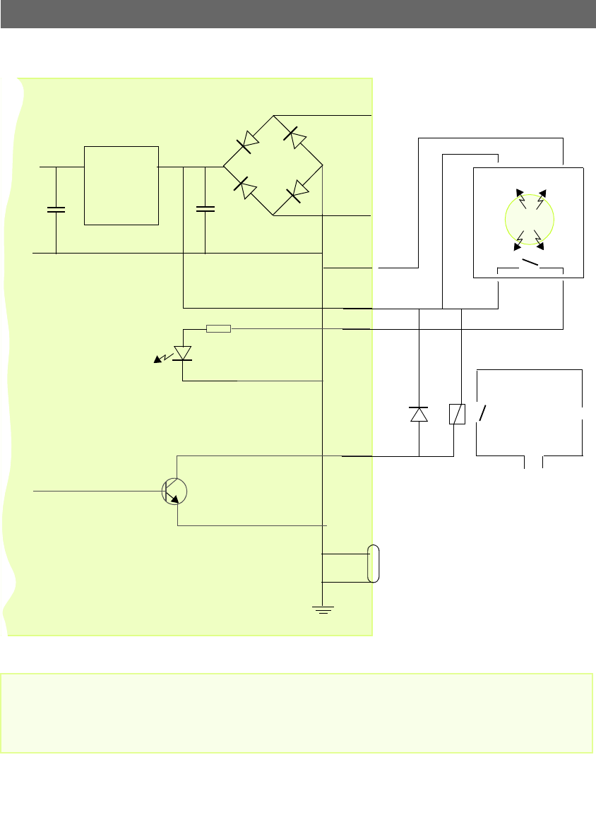
Schematic Connection Diagram of the I/O and RS232 Connector
Pins 1 and 2 are connected to the derived DC power for the unit, and can be used as an external power
feed for external equipment; such as an Infrared sensor. When connecting other equipment using this
connector, the maximum current of 50mA must be strictly observed. Failure to do so may cause a loss
of power to the unit and may even damage your camera.
AXIS 2100
o
o
GND.
Mode
Power
Supply
3.3V
!
!
!!
!
!
!
!
!
!
o
o
Switch
1
o
!
!
COM 1
!
!
GND PIN 5
2
o
!
o
!
4
3
Main Power
Appliance
o
o
o
x
o
o
o
o
o
o
o
o
Infrared Sensor
!
!!
!
-
+
Internal
~
PS-D
9 VA