


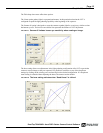
Page 23
Installation
TM/TMC-4200CL Series Progressive Scan Cameras
• Mount the camera on a large heat sink (camera bracket) made out of heat-conductive material like
aluminum.
• Make sure the flow of heat from the camera case to the bracket is not blocked by a non-conductive
material like plastic.
• Make sure the camera has enough open space around it to facilitate the free flow of air.
Please contact JAI at (800) 445-5444 or send an E-mail to imaging@pulnix.com if you have any
questions.
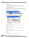
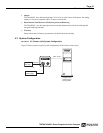
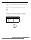
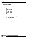
5.2.2 Connector Pin Configurations
5.2.2 (a) 12-Pin Connector
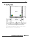
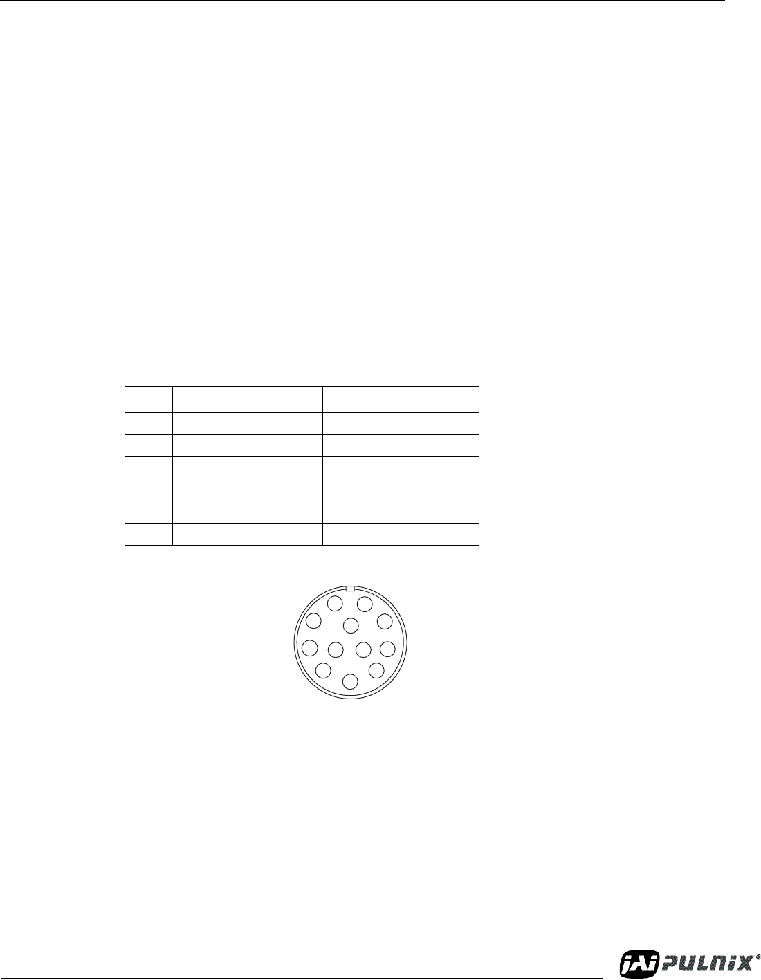
The TM-4200CL has a 12-pin Hirose connector for power input and signal integration. Pin #1 is
Ground and pin #2 is +12V DC. The pin-out table is shown below. Serial communication camera
control is accomplished by means of the Camera Link connector on the rear panel of the camera.
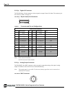
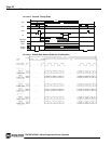
TABLE 1. 12-Pin Connector
FIGURE 36. Hirose Connector
Pin Description Pin Description
1 GND 7 VD in
2 +12V DC 8 Strobe
3 GND (analog) 9 HD in
4 Video out 10 NC
5 GND (digital) 11 Reserved
6 VINIT in 12 NC
1
2
3
4
5
6
9
8
7
11
12
10