


Page 24
Installation
TM/TMC-4200CL Series Progressive Scan Cameras
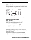
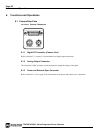
5.2.2 (b) Digital I/O Connector
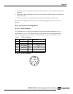
The TM-4200 has a 26-pin connector on the rear panel to output Camera Link data. The connector pin-
out is shown in Table 2 on page 24
FIGURE 37. 26-pin Camera Link Connector.
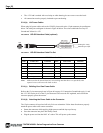
TABLE 2. Connector and Pin-out Configurations
Note: SerTC: Serial To Camera
SerTFG: Serial to Frame Grabber
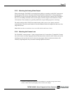
5.2.2 (c) Analog Output Connector
The TM-4200CL has a BNC connector on the rear panel to output the analog video signal. Analog
output is available to drive auto-iris lenses and troubleshooting.
Note: This analog signal is not an RS-170 (television format) signal that can be connected to a
standard CCTV monitor.
FIGURE 38. BNC Connector.
Camera Link Connector
Pin # Description I/O Pin # Description I/O
1 GND 14 GND
2 Tx OUT 0- Out 15 Tx OUT 0+ Out
3 Tx OUT 1- Out 16 Tx OUT 1+ Out
4 Tx OUT 2- Out 17 Tx OUT 2+ Out
5 Tx CLK OUT - Out 18 Tx CLK OUT+ Out
6 Tx OUT 3- Out 19 Tx OUT 3+ Out
7 SerTC+ In 20 SerTC- In
8 SerTFG- Out 21 SerTFG+ Out
9 VINIT In 22 VINIT+ In
10 Reserved In 23 Reserved In
11 EX-HD- In 24 EX-HD+ In
12 EX-VD+ In 25 EX-VD- In
13 GND 26 GND
1
1426
13