


Page 26
Installation
TM/TMC-4200CL Series Progressive Scan Cameras
• The +12V lead is marked with a red stripe or white lettering; be sure not to reverse the leads.
• All connections must be properly insulated to prevent shorting.
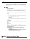
5.2.4 (b) JAI Power Cables
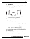
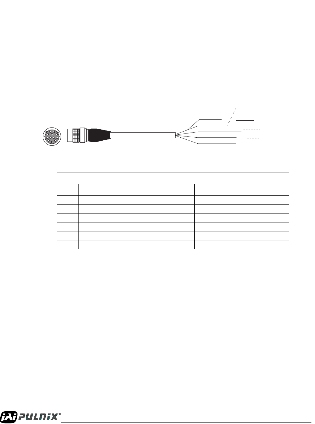
When using JAI power cables such as the 12P-02S, please refer to the 12-pin connector pin-out diagram
below. The cable pin-out diagram is shown in Figure 40 below. The color-coded leads use Gray for
Ground and Yellow for +12V.
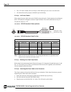
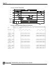
FIGURE 40. 12P-02S Interface Cable (optional)
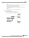
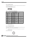
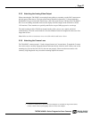
FIGURE 41. 12P-02S Interface Cable Pin Out
Note: Make sure that the unused leads are not touching and that there is no possibility that
exposed wires could cause the leads to short.
5.2.4 (c) Building Your Own Power Cable
Refer to the 12-pin connector pin-out in Figure 40 on page 26. Connect the Ground lead to pin #1, and
the +12V DC lead to pin #2 of the 12-pin connector. Power must be DC-regulated, and of sufficient
current to properly power the camera.
5.2.4 (d) Attaching the Power Cable to the Connector
The 12-pin connector is keyed and will only fit in one orientation. Follow these directions to properly
attach the power cable to the camera connector:
1. Rotate the connector while applying slight pressure until the keyways line up.
2. Press the connector into place until firmly seated.
3. Plug the power cord into the 100V AC socket. This will power up the camera.
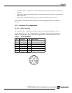
12P-02S Interface Cable
Pin# Lead Color Function Pin# Lead Color Function
1 Gray GND 7 Black coax VD Input
2 Yellow +12V DC 8 White coax shield Strobe out
3 Red coax shield GND (analog) 9 White coax HD Input
4 Red coax Video Out 10 Brown RXD
5 Orange coax shield GND (digital) 11 Blue Reserved
6 Orange coax VINIT IN 12 Black coax shield TXD
HD In (White Coax)
Video Out (Red Coax)
VD In (Black Coax)
Power (Yellow)
+12 V
GND (Gray)
}
Male
External sync input
Analog Ch. A only