


Page vii
List of Figures
List of Figures
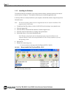
FIGURE 1. Setup installs Dual Tap AccuPIXel v 2.5.0 . . . . . . . . . . . . . . . . . . . . . . . . . . . . . . .2
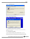
FIGURE 2. AccuPIXel Setup screen . . . . . . . . . . . . . . . . . . . . . . . . . . . . . . . . . . . . . . . . . . . . .3
FIGURE 3. Follow the installation directions . . . . . . . . . . . . . . . . . . . . . . . . . . . . . . . . . . . . . . .3
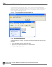
FIGURE 4. The screen grabber has an essential .dll file. . . . . . . . . . . . . . . . . . . . . . . . . . . . . . .4
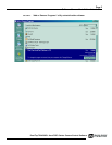
FIGURE 5. “Add or Remove Programs” utility uninstalls older software. . . . . . . . . . . . . . . . .5
FIGURE 6. Back of the TM/TMC 4200CL . . . . . . . . . . . . . . . . . . . . . . . . . . . . . . . . . . . . . . . .6
FIGURE 7. Main DualTap AccuPiXEL Window . . . . . . . . . . . . . . . . . . . . . . . . . . . . . . . . . . . .7
FIGURE 8. Setting up CamLink . . . . . . . . . . . . . . . . . . . . . . . . . . . . . . . . . . . . . . . . . . . . . . . . .8
FIGURE 9. Choose the desired frame driver .dll . . . . . . . . . . . . . . . . . . . . . . . . . . . . . . . . . . . .8
FIGURE 10. An error message appears if the .dll application is missing. . . . . . . . . . . . . . . . . . .8
FIGURE 11. The report frame is near the bottom of the window. . . . . . . . . . . . . . . . . . . . . . . . .9
FIGURE 12. Continuous mode operates the shutter from the camera settings. . . . . . . . . . . . . . . .9
FIGURE 13. Trigger mode uses a manual or sensor command to operate the shutter. . . . . . . . . .10
FIGURE 14. To use Programmable shutter speed, select Programmable: . . . . . . . . . . . . . . . . . .10
FIGURE 15. The Scan Area drop down box. . . . . . . . . . . . . . . . . . . . . . . . . . . . . . . . . . . . . . . .11
FIGURE 16. Enter the starting line number for a programmable scan. . . . . . . . . . . . . . . . . . . . .11
FIGURE 17. Click the Apply button after programming the scan. . . . . . . . . . . . . . . . . . . . . . . . .11
FIGURE 18. Gain is being set if the R Auto Gain box appears checked. . . . . . . . . . . . . . . . . .12
FIGURE 19. R Auto Offset box is checked only while the camera sets the command. . . . . . . . .12
FIGURE 20. Click the corresponding option button to set the tap. . . . . . . . . . . . . . . . . . . . . . . .13
FIGURE 21. Click the option button to select Video Depth. . . . . . . . . . . . . . . . . . . . . . . . . . . . .13
FIGURE 22. Checking “Enable Blemish Compensation” activates Image Pre-Processing. . . . .13
FIGURE 23. Set “Ctrl Signal” by clicking the option button matching your cabling. . . . . . . . . .13
FIGURE 24. Set “Trigger” by clicking the desired option button. . . . . . . . . . . . . . . . . . . . . . . . .14
FIGURE 25. Set “Positive” or “Negative” LUT. . . . . . . . . . . . . . . . . . . . . . . . . . . . . . . . . . . . . .14
FIGURE 26. Table drop down menu: . . . . . . . . . . . . . . . . . . . . . . . . . . . . . . . . . . . . . . . . . . . . . .14
FIGURE 27. Gamma.45 imitates human eye sensitivity when creating an image. . . . . . . . . . . .15
FIGURE 28. The knee setting activates when “Send Knees” is clicked. . . . . . . . . . . . . . . . . . . .15
FIGURE 29. The report frame shows the recent camera actions. . . . . . . . . . . . . . . . . . . . . . . .16
FIGURE 30. A table helps users understand the report screen. . . . . . . . . . . . . . . . . . . . . . . . . . .16
FIGURE 31. Use the “Option” menu to access the test pattern. . . . . . . . . . . . . . . . . . . . . . . . . .17
FIGURE 32. Use the “Option” menu to access the test pattern. . . . . . . . . . . . . . . . . . . . . . . . .17
FIGURE 33. Use the “Connectivity” menu to set buffer size. . . . . . . . . . . . . . . . . . . . . . . . . . .18
FIGURE 34. The “About” menu provides hardware and software information. . . . . . . . . . . . .18
FIGURE 35. CL (Camera Link) System Configuration . . . . . . . . . . . . . . . . . . . . . . . . . . . . . . .21
FIGURE 36. Hirose Connector . . . . . . . . . . . . . . . . . . . . . . . . . . . . . . . . . . . . . . . . . . . . . . . . . .23
FIGURE 37. 26-pin Camera Link Connector. . . . . . . . . . . . . . . . . . . . . . . . . . . . . . . . . . . . . . . .24
FIGURE 38. BNC Connector. . . . . . . . . . . . . . . . . . . . . . . . . . . . . . . . . . . . . . . . . . . . . . . . . . . .24
FIGURE 39. 3M Camera Link Cable . . . . . . . . . . . . . . . . . . . . . . . . . . . . . . . . . . . . . . . . . . . . .25
FIGURE 40. 12P-02S Interface Cable (optional) . . . . . . . . . . . . . . . . . . . . . . . . . . . . . . . . . . . .26
FIGURE 41. 12P-02S Interface Cable Pin Out . . . . . . . . . . . . . . . . . . . . . . . . . . . . . . . . . . . . . .26
FIGURE 42. Camera Connectors . . . . . . . . . . . . . . . . . . . . . . . . . . . . . . . . . . . . . . . . . . . . . . . .28
FIGURE 43. Digital Video Output . . . . . . . . . . . . . . . . . . . . . . . . . . . . . . . . . . . . . . . . . . . . . . .29
FIGURE 44. Camera Timing Chart . . . . . . . . . . . . . . . . . . . . . . . . . . . . . . . . . . . . . . . . . . . . . . .30
FIGURE 45. Digital Data Output Order for Configuration . . . . . . . . . . . . . . . . . . . . . . . . . . . .30
FIGURE 46. Field Video Timing--Continuous Mode . . . . . . . . . . . . . . . . . . . . . . . . . . . . . . . . .31
FIGURE 47. Bayer 1 . . . . . . . . . . . . . . . . . . . . . . . . . . . . . . . . . . . . . . . . . . . . . . . . . . . . . . . . .33
FIGURE 48. Bayer 2 . . . . . . . . . . . . . . . . . . . . . . . . . . . . . . . . . . . . . . . . . . . . . . . . . . . . . . . . . .33
FIGURE 49. 2x2 Binning . . . . . . . . . . . . . . . . . . . . . . . . . . . . . . . . . . . . . . . . . . . . . . . . . . . . . .34
FIGURE 50. Sub-sampling Digital Zoom . . . . . . . . . . . . . . . . . . . . . . . . . . . . . . . . . . . . . . . . . .35
FIGURE 51. Sub-sampling Digital Zoom 2x . . . . . . . . . . . . . . . . . . . . . . . . . . . . . . . . . . . . . . .35