


Setting the Time Data
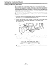
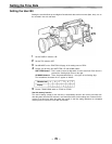
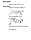
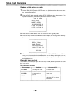
External Lock Operation Procedure
3
2
1
1
Set the POWER switch to ON.
2
Set the F-RUN/R-RUN switch to F-RUN
3
Set the DISPLAY switch to TC.
4
Supply reference time code and reference video signals with a phase relationship which
meets the time code standards to the TC IN and GENLOCK IN connectors, respectively.
This locks the built-in time code generator to the reference time code. After about 10 seconds
have passed since the time code generator was locked, the external lock status is maintained
even if the external reference time code is disconnected. However, if the reference time code is
disconnected during recording (REC), the servo lock will be thrown out of order.
<Note>
When the external locking operation is performed, the time code is locked instantly to the external
time code and the same value as the external code value appears in the counter display position.
Do not set the VTR to recording mode for several seconds until the sync generator has stabilized.
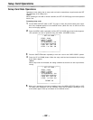
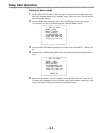
Setting Time Data
User bit setting during external locking
When the time code is locked to an external source, only the time data is locked to the time data of
the time code from the external source. Accordingly, the user bit can be set independently for
each unit. The user bit can also be locked to the user bit of the time code from the external source.
Consult your dealer for a detailed explanation.
Releasing the external lock
Stop supplying the external time code and then set the F-RUN/R-RUN switch to R-RUN.
Switching the power supply from the battery to an external power supply during external
locking
In order to maintain power supply continuity for the time code generator, connect the external
power supply to the DC IN connector before unplugging the battery pack. If the battery pack is
unplugged first, the external locking continuity of the time code cannot be assured.
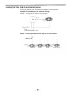
Synchronizing the camera section to an outside source during external locking
While the time code is locked to an external source, the camera section is genlocked by the refer-
ence video signal input to the GENLOCK IN connector.
- 80 -