


16
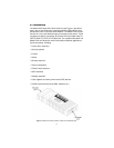
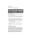
Default Settings
Default settings for the DIP switches are as follows:
Detailed Switch Settings
This section provides detailed information about the function of each DIP
switch and lists all possible settings.
• Switch 1: Configuration Reset. Set this switch to the ON position and
power cycle the unit to reset to the factory default configuration param-
eters.
Note
This will not change the factory assigned NIC/MAC address.
• Switch 2: DCE/DTE on Configuration Reset. When a configuration
reset is being performed via Switch 1 (above), set this switch to the ON
position to force the serial interface to DTE or to the OFF position to
force the serial interface to DCE.
Note
This switch is ONLY read when the configuration is reset
through Switch 1 (above).
• Switch 3: Not Used. This switch is not used and must remain in the
OFF position.
• Switch 4: Not Used. This switch is not used and must remain in the
OFF position.
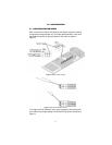
3.2 SOFTWARE CONFIGURATION
The Model 2120 features a menu-driven command system that enables
the configuration of the 2120 software via the serial interface using a VT-
100 terminal or emulation session or over the LAN using a Telnet ses-
sion. Since the Model 2120 is not pre-configured with an IP address for
your network, initial configuration of the Model 2120 is performed via the
serial interface (See “Initial Unit Configuration” on page 21.). Once initial
configuration is complete with a static or dynamically assigned IP
address and the Model 2120 is connected to the LAN, configuration
parameters can be modified over the LAN using a Telnet session. The
Table 1:
Default Settings
Position Function Factory Default
SW1 Configuration Reset OFF
SW2 DCE/DTE on Config Reset OFF
SW3 Not Used (Must Be OFF) OFF
SW4 Not Used (Must Be OFF) OFF