4.4 The Pan/Zoom Display Window
This window provides you with a graphical representation of where and how the digitized image relates
to the detector on your camera, and the tools to modify those setting. The regions indicated in this
display are not drawn to scale. This window can be minimized but not resized. In this window you can:
• Hardware Zoom-in and Zoom-out.
• Soft Zoom-in and Zoom-out.
• Pan the Window vertically and horizontally.
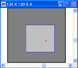
The title bar indicates the current image size that is being captured and stored into the frame buffer,
and the current resolution setting. Because this window is kept as small as possible the image size text
is often truncated. Move the mouse pointer into the title bar and a hints display will pop-up and show
the full text.
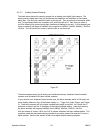
The outer White area represents the photosensitive surface area of the camera’s detector.
The Red Dot indicates the approximate placement of the X,Y origin. You can not change or affect the
location of the origin in this window. To make changes, see the Origin Location edit control in the
Beam Display dialog box.
Figure 51
4.4.1 Hardware Zooming
The Dark Gray region depicts the Capture window, i.e., the region on the camera detector where
the image is being acquired. Because this relates to how the frame grabber hardware is configured, it
is referred to as the Hardware Zoom box. If you Double-left-click inside this box, you will cause
this box to Zoom-in by a factor of 2x. If you Double-left-click outside this box you will Zoom-out.
Observe that the image resolution will increase as you zoom-in; x4.., x2.., x1.., is in the increasing
direction. As you zoom-in the image size will remain the same, until the resolution can no longer
increase. At this point the image size will start to decrease, making the apparent size of the image
larger.
The center of the Hardware Zooming action will be the intersection point of the Cursors. If the
Cursors are turned Off, the zoom center will be about the center of the current frame. See also
Zooming Constraints in Section 4.4.4.
Operator’s Manual LBA-PC
Doc. No. 10654-001, Rev 4.10
111


