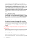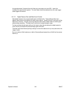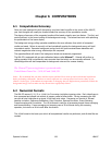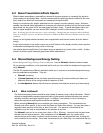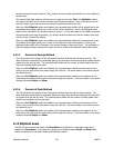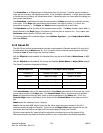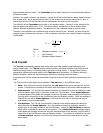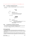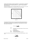
The standard deviations are derived from the variances of the energy distributions and are equal to
the standard deviations squared. The variances are:
σ
x
yx
yx
xx Zxy
Zxy
2
2
=
−⋅
∑
∑
∑∑
()(,
(, )
)
σ
y
yx
yx
yy Zxy
Zxy
2
2
=
−⋅
∑
∑
∑∑
()(,
(, )
)
Where:
Z = the intensity of the pixel
x and y are the coordinates of the centroid
Only beam propagation factors based on beam widths and divergence angles derived from the second
moments of the energy density distribution function, will allow one to predict how a beam will
propagate. Other definitions of the beam widths and divergence angles may be used, but they must
be shown to be equivalent to the second moment definitions for computing the correct beam
propagation.
To make an accurate measurement of the beam widths with the LBA-PC you must aperture the beam
inside a Drawn or Auto Aperture. The aperture must be approximately 2x the size of the beam. The
Auto Aperture feature of the LBA-PC will automatically provide such an aperture under most operating
conditions. It can be used in combination with a Drawn Aperture if needed. If your beam size is
already equal to about 1/2 the beam display window, then you can usually get by without drawing an
aperture, just be sure to center the beam in the window.
6.11.2 Knife Edge Method
Beam widths are computed using special algorithms that simulate knife-edge techniques. The method
employed in the LBA-PC borrows from two sources. They are:
ISO 11146 Lasers and laser-related equipment—Test methods for laser beam parameters— Beam
Widths, divergence angle and beam propagation factor
Note this document is being revised and split into three parts:
• 11146-1, Part 1: Stigmatic and simple astigmatic beams
• 11146-2, Part 2: General astigmatic beams
• 11146-3, Part 3: Alternative test methods and geometrical laser beam classification and
propagation
And from the IEEE Journal of Quantum Electronics, Vol 27, No 4, April 1991 Choice of Clip Levels for
Beam Width Measurements Using Knife-Edge Techniques by Siegman, Sasnett and Johnston.
The LBA offers the operator two methods for computing Knife Edge beam widths. The 90/10
method presets the Clip% values to 90% and 10% respectively, and the Multiplier to 1.561.
These are the recommended values based upon the above Siegman, et al. paper, and are very
compatible with CCD camera noise figures. These values are perfectly correct for computing an
Operator’s Manual LBA-PC
Doc. No. 10654-001, Rev 4.10
133


