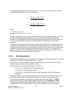
Ultracal! every 10 to 15 minutes, or whenever you think your camera may have strayed. This drift
can be observed as changes in the background noise image. Un-illuminated areas will appear as gray
and dark violet (almost black) random noise. If the background starts to look too gray then the
baseline is drifting negative. If too dark, then the baseline is drifting positive. Note: These colors
apply to the Continuous 128 color palette. They change depending upon the palette selection.
6.5 Clip Level
What is the Clip Level and how is it used?
The clip level is a processed
energy
pixel value. Only those pixel values that exceed the clip level are
used in computing the following results:
• Beam Widths, if Percent of Energy or Peak methods are selected.
• Centroid Location.
• Elliptical beam Orientation.
• Top Hat: Mean, Standard Deviation, Min and Max, when in Data mode only.
• Effective Area.
Depending upon the Beam Width Method, the clip level value is determined as follows:
• With the 4-Sigma and Knife-Edge methods and with the Top Hat results disabled, the LBA
totals the pixel
energy
values in descending order until it finds the pixel which causes the sum to
exceed 86.5% of the total
energy
value. The raw
energy
value of this pixel becomes the clip
level.
• With the 4-Sigma and Knife-Edge methods and with the Top Hat results enabled, the LBA
sets the clip level to the value that is equal to 80% of the current peak
energy
value.
• With the Percent of Energy method, the LBA totals the pixel energy values in descending order
until it finds the pixel which causes the sum to exceed the set Clip% of the total
energy
value.
The
energy
value of this pixel becomes the clip level.
• With the Percent of Peak method, the LBA sets the clip level to the value that is equal to the
set Clip% of the current peak
energy
value.
The number of pixels with values above the clip level establishes the Effective Area of the beam. The
locations of the pixels with values above the clip level are used to determine the beam's Centroid
Location and Elliptical beam Orientation.
Note: When using a Knife Edge method, the Clip% value relates only to the Knife Edge measurement process, and
not to the above Clip Level description.
6.6 Total Energy
The cameras used with the LBA-PC are not calibrated to directly provide
energy
of a laser beam. The
Energy of Beam dialog box edit control lets you calibrate the LBA-PC to the
energy
of your laser. You
must measure the
energy
of your beam using an external measuring device, then enter the
energy
here. The value entered must be the total
energy
of the beam for the frame currently displayed. For
accurate results, the beam must fit inside of the current Pan/Zoom window.
If you enter a calibrated value of zero, the Total, Peak, Gauss Height(s), and Top Hat results are
displayed as processed digitizer values. Any entry other than zero will immediately appear as the Total
Operator’s Manual LBA-PC
130


