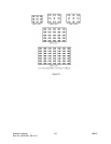
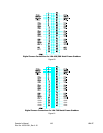
Signal definitions are as follows: References to LBA settings are found in either the Camera or
Camera Advanced dialog boxes. For digital cameras, set the Sync Source to Digital.
PCLK+/-
Connect your camera’s pixel clock to this input. Either the rising or falling edge of this signal
will denote the time when your camera’s pixel data should be sampled. If your camera data is
to be sampled by the falling edge of PCLK+, set the ERC Polarity to Positive. If your camera
data is to be sampled by the rising edge of PCLK+, set the ERC Polarity to Negative. Pixel clock
frequencies below 15MHz will allow large mega-pixel cameras to interface with the largest
image sizes. Cameras with high clock frequencies will require a reduction of the image size that
can be acquired. We have successfully interfaced cameras with clock rates at 25MHz, but with
a loss in image width. This will vary from camera to camera depending upon how the image is
formatted.
/HSYNC+/-
Connect your camera’s horizontal sync (or start of line/row) to this input. If /HSYNC+ is a
negative going pulse set the Sync Polarity to Negative. If /HSYNC+ is a positive going pulse set
the Sync Polarity to Positive. Note the polarity of the HSYNC and VSYNC signals must be the
same.
/VSYNC+/-
Connect your camera’s vertical sync (or start of frame/field) to this input. If /VSYNC+ is a
negative going pulse set the Sync Polarity to Negative. If /VSYNC+ is a positive going pulse set
the Sync Polarity to Positive. Note the polarity of the /HSYNC+ and /VSYNC+ signals must be
the same.
FIELD+/-
This signal is only used when the camera Scan Mode is Interlaced. Most digital cameras are
sequentially scanned, i.e. Non-interlaced. If your camera is interlaced, this signal will indicate
to the LBA which field is being input. FIELD+ must go high during the Odd or 1st field time,
and must go low during the Even or 2nd field time. It should change state at the beginning of
VSYNC.
VD11-0+/-… LBA-400/500
Connect the digital data signals to these inputs. VD11 is the MSB and VD0 is the LSB. Connect
the MSB from your camera to VD11. Unused connections must always involve the LSB’s. VD+
must be a logic high to denote a true condition of a data bit. Set the Pixel Bits value to the
number of data connections supported. Note: If the output from your digital camera is in a
signed two’s compliment data format, connect the sign bit to VD11, and the MSB data to VD10.
The Pixel Bits entry should be a negative value for signed data. For example: If your data is a
12 bit signed two’s compliment format, enter a -12 for the Pixel Bits.
Operator’s Manual LBA-PC
150


