


Locations and Functions of Parts and Controls
13
Chapter 1 Overview
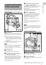
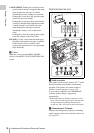
a LIGHT switch
Determines how a video light connected to the
LIGHT connector (see page 14) is turned on and
off.
AUTO: When the POWER switch of the video
light is in the on position, the video light is
turned on automatically while the camcorder
is recording.
MANUAL: You can turn the video light on or off
manually, using its own switch.
Note
When the camcorder is set for recording in Picture Cache
mode, it is not possible to turn on the light before
operation to start recording is carried out (or while data
is being stored in memory).
b POWER switch
Turns the main power supply on and off.
c DC IN (DC power input) connector
(XLR type, 4-pin, male)
To operate the camcorder from an AC power
supply, connect an optional DC power cord to this
terminal and then connect the cord to the DC
output terminal of the BC-L70, BC-L160, or
another battery charger.
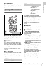
d DC OUT 12V (DC power output)
connector (4-pin, female)
Supplies power for an optional WRR-860A/861/
862 UHF Synthesized Diversity Tuner
(maximum 0.5 A).
Do not connect any equipment other than the
UHF synthesized diversity tuner.
e Battery attachment shoe
Attach a BP-GL95/GL65/L80S/L60S Battery
Pack. Alternatively, you can attach an AC-
DN2B/DN10 AC Adaptor to operate the
camcorder on AC power supply.
For details, see “Preparing a Power Supply”
(page 32).
For details, see “Attaching a UHF Portable Tuner
(for a UHF Wireless Microphone System)”
(page 43).
Note
For your safety, and to ensure proper operation of the
camcorder, Sony recommends the use of the following
battery packs: BP-GL95, BP-GL65, BP-L60S, and
BP-L80S.
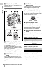
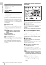
a Shoulder strap fitting
Attach the supplied shoulder strap (see page 45).
b Accessory fitting shoe
Attach an optional accessory such as a video light
(see page 45).
Locations and Functions
of Parts and Controls
Power Supply
Accessory Attachments