


Locations and Functions of Parts and Controls
24
Chapter 1 Overview
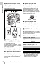
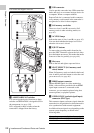
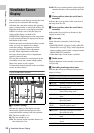
d AUDIO IN selectors
Select the audio source you connect to the
AUDIO IN CH1/CH2 connectors.
LINE: When connecting a stereo amplifier or
other external audio signal source
MIC: When connecting a microphone that does
not require 48 V power supply
+48V: When connecting a microphone that
requires 48 V power supply
e HD/SD SDI OUT connector (BNC type)
Outputs an HDSDI or SDSDI signal (with
embedded audio). The output from this connector
can be turned on and off with OPERATION
>Input/Output >SDI Output in the setup menu.
f AUDIO IN CH1/CH2 (audio channel 1
and channel 2 input) connectors (XLR
type, 3-pin, female)
These are audio input connectors for channels 1
and 2 to which you can connect audio equipment
or a microphone.
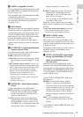
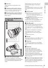
g Bottom cover
This is provided for protecting the cables
connected to the connectors on the rear panel.
By loosening the screws which retain the cover to
the bottom of the camcorder, you can adjust the
position of the cover depending on the size and
shape of the microphone or audio cable plugs.
After adjusting the position, tighten the screws to
secure the cover.
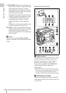
h AUDIO OUT connector (XLR type, 5-
pin, male)
Outputs the audio signals recorded on audio
channels 1 and 2 or audio channels 3 and 4. The
audio signals are selected by the MONITOR
switch.
i REMOTE connector (8-pin)
Connect a remote control unit, which makes it
possible to control the camcorder remotely.
Note
Before connecting/disconnecting the Remote Control
Unit to/from the camcorder, be sure to turn off the
camcorder POWER switch.
j i.LINK (HDV/DV) connector (6-pin,
IEEE1394 compliant, S400)
To input and output HDV/DV streams, connect to
an HDV/DV device.
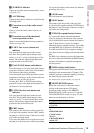
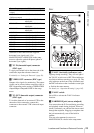
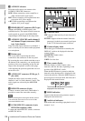
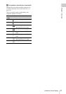
a Timecode status
NDF: Appears when non-drop-frame timecode is
selected.
EXT-LK: Appears when the internal timecode
generator is locked to an external signal input
to the TC IN (timecode input) connector.
b Counter display mode
Shows the type of information selected by the
DISPLAY switch to be displayed in the time
counter display.
COUNTER: Counter values
TC: Timecode
U-BIT: User bits data
c Time counter display
Switches displays of time counter values,
timecode, and user bits data, depending on the
position of the DISPLAY switch.
When the HOLD button is pressed to hold the
timecode value, the timecode is displayed in the
format shown below. When the HOLD button is
pressed again to release the hold, the timecode is
displayed in the normal format.
d HOLD indication
Appears when the timecode generator output is
displayed in the hold mode.
e Audio level indicators
Indicate the audio recording or playback levels of
channels 1 to 4.
Monochrome LCD Panel
The three dots indicates that timecode is
displayed in the hold mode.