


DEFINITY Enterprise Communication Server Release 9
Getting Started with the Avaya R300 Remote Office Communicator
Issue 1
November 2000
Avaya R300 Specifications and Network Design
19Setting up the Avaya R300
2
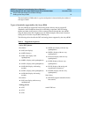
The following cabling is required for the Avaya R300 Interconnect module:
■ Power cord (appropriate for country of installation)
■ Cable to connect analog and DCP stations to the unit
Additionally, all network cable going to the Avaya R300 should be CAT 5 to provide the
best voice quality possible.
For more information about cabling with the Avaya R300, see MAX 3000 Basic
Installation and Configuration Guide, Appendix C, Cables and Connectors.
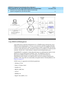
Wall field cabling
If you prefer to deploy the Avaya R300 with your existing wall field cabling, you can
connect the Combo Blade Y-cable to a conventional wall field panel. The Avaya R300
Combo Blade must be powered with the Y-cable or the Avaya R300 will not function. The
Y-cable has 50-pin, male and female connectors, which allows you to use standard,
Telcom 50-pin cables to extend the reach of the Y-cable to the wall field location. The
analog power plug has a gender changer, which makes the Y-cable compatible with
110-volt hardware.
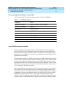
50-pin male connector on Y-cable
The 50-pin male connector on the Y-cable provides a standard cut-down configuration for
the 24, two-wire sets. For example:
■ DCP-Tip 1 is connected to pin 26
■ DCP-Ring 1 is connected to pin 1
■ DCP-Tip 2 is connected to pin 27
■ DCP-Ring 2 is connected to pin 2
This configuration pattern would continue for up to 24 DCP sets. The auxiliary power for
the DCP sets is delivered on pins 7 & 8 of each set. Pin 7 is -48Vdc lead and pin 8 is
ground (+48Vdc) lead.
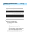
The maximum power level for each DCP set is 6 watts or a 120-watt maximum of 48Vdc.
The voltage range for operation must be greater than 42.5Vdc and less than 56.5Vdc. The
current limit for each DCP set is 170Ma.