


DEFINITY Enterprise Communication Server Release 9
Getting Started with the Avaya R300 Remote Office Communicator
Issue 1
November 2000
Avaya R300 Specifications and Network Design
20Setting up the Avaya R300
2
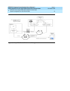
50-pin female connector on Y-cable
The 50-pin female connector on the Y-cable provides the communication flow for the two
analog stations and two analog loop start trunks, and provides the source of -48 volts to the
Combo Blade (for phantom power of DCP sets).
When using analog sets, make the following pin connections:
1. Analog line-Tip 1 is connected to pin 26
2. Analog line-Ring 1 is connected to pin 1
3. Analog line-Tip 2 is connected to pin 30
4. Analog line-Ring 2 is connected to pin 5
5. Analog trunk-Tip 1 is connected to pin 42
6. Analog trunk-Ring 1 is connected to pin 17
7. Analog trunk-Tip 2 is connected to pin 46
8. Analog trunk-Ring 2 is connected to pin 21
The analog and power female connector on the Y-cable supplies 30 watts of -48Vdc to the
Combo Blade (25 watts under load condition). The battery (-48Vdc) is connected to pins 9
& 13 while the ground (+48Vdc) is supplied on pins 34 & 38. You should provide both
pairs of signals to maintain an appropriate impedance for the source to the -48 volts.
The voltage range for operation must be greater than 42.5Vdc and less than 56.5Vdc. The
current must be limited to 750ma.
NOTE:
Power units must have safety and emission approvals appropriate for the country of
installation. The power applied to the Combo Blade may require FCC part 68
registration or other country telco registration.
NOTE:
Power supplied to the Avaya R300 Combo Blade must meet the following
standards:
■ Power Required: 48Vdc at 150W with a minimum of 42.5Vdc and a
maximum of 56.5Vdc
■ Current Limit: Phantom Power 750Ma, Auxiliary Power 170Ma per DCP
set
■ Line and Load Regulation: plus or minus 2%
■ Minimum Load: 0 Watts must regulate at no load
■ Protection: Overvoltage, Overcurrent