


DEFINITY Enterprise Communication Server Release 9
Getting Started with the Avaya R300 Remote Office Communicator
Issue 1
November 2000
Avaya R300 Installation and Upgrade
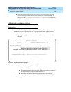
41Installing the Avaya R300
3
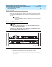
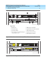
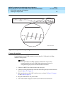
Table 7. Avaya R300 front-panel lights
Light Description
Power Green when the Avaya R300 power is on.
Fault Yellow in one of two cases. Either a hardware
self-test is in progress or there is a hardware
failure.
When a hardware self-test is in progress, the light
is on. If any type of hardware failure occurs, the
light flashes. If the failure is isolated to an
expansion card, the Avaya R300 may continue
functioning without the expansion card.
Data Green at power-up and thereafter when packets are
detected on the Ethernet interface.80
Alarm Amber at power-up. Thereafter, on indicates a
low-power detection (Avaya R300 sends an SNMP
trap), WAN alarm, or trunk out-of service (for
example, during line loopback diagnostics). WAN
alarms include Loss of Sync, Red Alarm, Yellow
Alarm, and All Ones (or AIS).
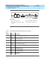
Table 8. Avaya R300 back-panel lights
Light Description
LNK During 10 Mbps operation, indicates Link Valid
status. During 100 Mbps operation, indicates
scrambler lock and receipt of valid Idle codes. The
light is green when on.
TX Indicates transmitter is active. The light is green
when on.
DPLX Indicates that the port is in Full Duplex Mode. The
light is green when on. When the light is off, the
port is in Half Duplex Mode.
100BT Indicates that 100 Mbps operation is selected for
the UTP port. the light is green when on.
RX Indicates that the receiver is active. The light is
green when on.
COL Indicates a collision. The light is amber when on.