


DEFINITY Enterprise Communication Server Release 9
Getting Started with the Avaya R300 Remote Office Communicator
Issue 1
November 2000
Avaya R300 Specifications and Network Design
23Bandwidth engineering considerations
2
Remote Office WAN access trunks
The Avaya R300 offers a variety of WAN interfaces. The North American model offers
two T1 interfaces. The Global model offers two E1 interface interfaces. These interfaces
are referred to as “digital trunks”. These interfaces may be used for network control/bearer
communication to the host switch site, or local access trunks (to the local network central
office).
Since the traffic within T1/E1 trunks is actually a group of individually switched DS0
(64Kbps) pipes, traffic within these T1/E1 facilities can be directed to two or more
destinations. Therefore, both local trunk access traffic and traffic destined for the main
switch host site may use a given Avaya R300 WAN trunk facility.
In Release 1.1 of the Avaya R300, you have access to the two analog loop-start trunks to
provide additional bandwidth (two DS0's). You can use this added bandwidth for standard
operational PSTN trunk bandwidth.
MultiVoice DSP resources in the Avaya R300
In the Avaya R300, the bearer conversion (from TDM based traffic to IP based traffic) is
performed in a Multi-Voice DSP module. The DSP-16 module, which supports 16
channels of TDM voice to IP voice conversion, is now available. The DSP-30 module,
which supports 30 channels of TDM voice to IP voice conversion, will be available in the
near future.
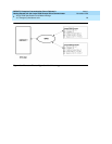
The Connection Management software module in the Avaya R300 determines if both
parties are connected via local ports (either local access trunks or DCP/analog station sets)
on the Avaya R300 unit. If both parties are local, the switch connection will be offered
over a TDM based connection with that Avaya R300. Otherwise, a VOIP channel is
utilized for each party that is connected.
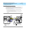
Engineering bandwidth components
The five networking components must be engineered appropriately. A general equation
might be: Total Bandwidth = (Aggregate voice bandwidth) + (Aggregate data bandwidth).
■ Aggregate Voice Bandwidth = (Aggregate Voice Bearer bandwidth) + (Aggregate
signaling bandwidth associated with these voice applications)
■ Aggregate data bandwidth is that bandwidth devoted for IP traffic between host
and remote sites.
Aggregate voice bearer bandwidth is a function of the call traffic model. You would take
the amount of equipped stations (DCP, analog), together with the amount of equipped
local access trunks), and calculate the amount of average traffic that is networked back to
the DEFINITY host site. A typical configuration could have as many as half of the calls be
networked back to the DEFINITY. In this example, you would multiply the number of
endpoints by the CODEC used, to determine needed bandwidth.
NOTE:
The bandwidth for call signaling and registration traffic is estimated to be two DS0's
in size for a full deployment of 24 digital stations, 2 analog stations, and a full
complement of trunk group members.