


Instruction Manual
748467-A
January 2002
1-4 Description and Specifications Rosemount Analytical Inc. A Division of Emerson Process Management
Model MicroCEM
Opto-Pneumatic Method
In the opto-pneumatic method, a thermal
radiator generates the infrared radiation
which passes through the chopper wheel.
This radiation alternately passes through
the filter cell and reaches the measuring
and reference side of the analysis cell
with equal intensity. After passing another
filter cell, the radiation reaches the pneu-
matic detector.
The pneumatic detector compares and
evaluates the radiation from the measur-
ing and reference sides of the analysis
cell and converts them into voltage sig-
nals proportional to their respective inten-
sity.
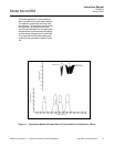
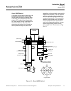
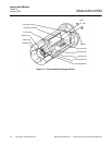
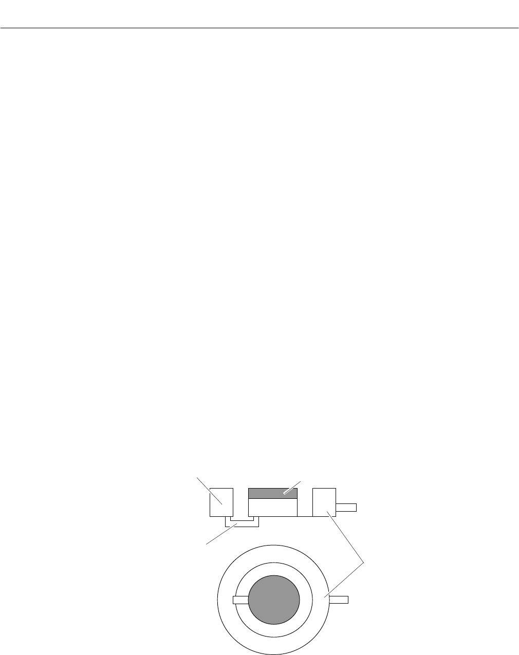
The pneumatic detector consists of a gas-
filled absorption chamber and a compen-
sation chamber which are connected by a
flow channel in which a Microflow filament
sensor is mounted. This is shown in Fig-
ure 1-2.
In principle the detector is filled with the
infrared active gas to be measured and is
only sensitive to this distinct gas with its
characteristic absorption spectrum. The
absorption chamber is sealed with a win-
dow which is transparent for infrared ra-
diation. The window is usually Calcium
Fluoride (CaF
2
).
When the infrared radiation passes
through the reference side of the analysis
cell into the detector, no pre-absorption
occurs. Thus, the gas inside the absorp-
tion chamber is heated, expands and
some of it passes through the flow chan-
nel into the compensation chamber.
When the infrared radiation passes
through the open measurement side of
the analysis cell into the detector, a part
of it is absorbed depending on the gas
concentration. The gas in the absorption
chamber is, therefore, heated less than in
the case of radiation coming from the ref-
erence side. Absorption chamber gas be-
comes cooler, gas pressure in the
absorption chamber is reduced and some
gas from the compensation chamber
passes through the flow channel into the
absorption chamber.
The flow channel geometry is designed in
such a way that it hardly impedes the gas
flow by restriction. Due to the radiation of
the chopper wheel, the different radiation
intensities lead to periodically repeated
flow pulses within the detector.
The Microflow sensor evaluates these
flow pulses and converts them into elec-
trical pulses which are processed into the
corresponding analyzer output.
Figure 1-2. Opto-Pneumatic Gas Detector
Flow channel with
Microflow sensor
Absorption chamber
CaF
2
Window
Compensation chamber