


Instruction Manual
748467-A
January 2002
Rosemount Analytical Inc. A Division of Emerson Process Management Installation 2-3
Model MicroCEM
2-3 GASES
NOTE
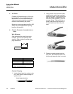
For external gas lines, the use of new tub-
ing throughout is strongly recommended.
The preferred type is teflon or stainless
steel, sealed at both ends.
a. Connection
Besides sample gas, the MicroCEM re-
quires other gases for operation. In most
cases, one or more Calibration Standards
must be provided. These should be cylin-
ders of gas which closely resemble the
expected sample, both in species and
concentrations. These calibration gases
are normally introduced into the system
as an input to the Sample Conditioning
Plate Option or sample conditioning may
be provided by others.
Each gas cylinder should be equipped
with a clean, hydrocarbon free two-stage
pressure regulator with indicating gauges
of approximately 0 to 3000 psig (0 to 20.7
bar) for cylinder pressure and 0 to 100
psig (0 to 6.7 bar) for delivery pressure.
Pressure regulators should have a metal-
lic as opposed to elastomeric diaphragm,
and provide for ¼ inch compression fitting
outlet and should be LOX clean.
NOTE
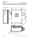
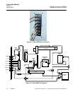
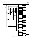
All connections specified in the In-
stallation Drawing, in conjunction with
the Application Data Sheet, should be
made.
b. Conditioning
All gases must be supplied to the ana-
lyzer as conditioned gases! When the
system is used with corrosive gases, it
must be verified that there are no gas
components which may damage the gas
path components.
The gas conditioning must meet the fol-
lowing conditions:
•
Free of condensable constituents
•
Free of dust above 2 µm
•
Free of aggressive constituents which
may damage the gas paths
•
Temperature and pressure in accor-
dance with the specifications
When analyzing vapors, the dewpoint of
the sample gas must be at least 10 °C
below the ambient temperature in order to
avoid the precipitation of condensate in
the gas paths.
An optional barometric pressure compen-
sation feature can be supplied. This re-
quires a pressure sensor with a range of
800 – 1,100 hPa. The concentration val-
ues computer by the detectors will then
be corrected to eliminate erroneous
measurements due to changes in baro-
metric pressure.
The gas flow rate must be in the range of
0.2 l/min to a maximum of 1.5 l/min. A
constant flow rate of 1 l/min is recom-
mended.
NOTE
The maximum gas flow rate for par-
amagnetic oxygen detectors is 1.0
l/min!