


Instruction Manual
748467-A
January 2002
Rosemount Analytical Inc. A Division of Emerson Process Management Installation 2-5
Model MicroCEM
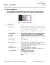
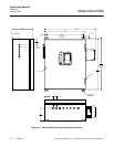
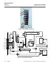
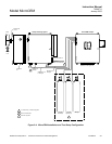
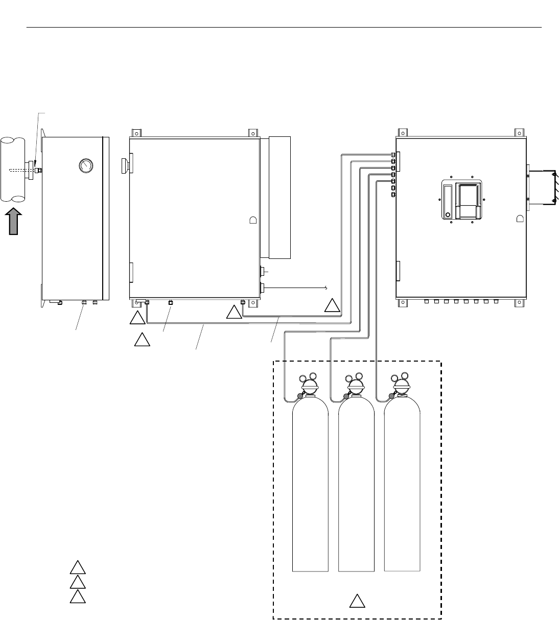
Figure 2-4. MicroCEM Installation and Test Setup Configuration
3
¼” Teflon tubing. Customer supplied.
2
Drain to safe location.
1
Customer supplied.
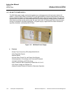
Electrical connections. See
Section 2-4 and Figure 2-5.
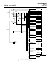
MicroCEM Analyzer
Sample Handling System
Nitrogen
O
2
/ NO
High Range
O
2
/ NO
Mid Range
Dry Contact
Initiate Auto Calibration
1
1
Sample
Flow
Stack
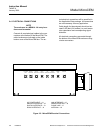
Sample Inlet
½” FPT
Instrument
Air
Atmospheric
Pressure
2
Sample From
Analyzer
Calibration Line
to Analyzer
3
3
Power In
115 VAC 60Hz 5A