


Instruction Manual
748467-A
January 2002
Rosemount Analytical Inc. A Division of Emerson Process Management Maintenance and Service 5-5
Model MicroCEM
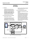
5-5 CHEMILUMINESCENSE DETECTOR AS-
SEMBLY
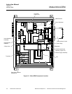
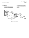
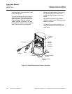
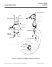
Refer to Figure 5-4 and Figure 5-5.
a. Reaction Chamber
Removal
Disconnect the stainless steel tubing lines
at the Gyrolok fittings. Remove the (4)
nuts holding the Detector Assembly to
the chassis. Disconnect the plug from
connector J1 on the Signal Board and
remove the assembly from the chassis.
NOTE
Heatsink Compound. Care should be
taken to avoid getting heatsink com-
pound on optical surfaces. If this sub-
stance is removed during the
disassembly process, a zinc ox-
ide-filled, silicone grease (e.g., Dow
Corning 340 or EG&G Wakefield Engi-
neering's Series 120 Thermal Joint
Compound) be reapplied in the re-
assembly of this component.
Although the heater and thermostat can
be removed to facilitate handling, contact
with the white heatsink compound can be
minimized by leaving these items in place.
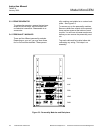
Remove the (2) screws holding the top
plate of the Detector , and move the plate
along the wires and away from the De-
tector .
Remove the (2) screws holding the tube
assembly in place. Hold the tubing with
one hand while inverting the Detector
Housing with the other, allowing the Re-
action Chamber O-ring and window to be
removed from below.
Installation
To reinstall, hold the housing in the in-
verted position while sliding the Reaction
Chamber O-ring and window into position
and the tubing into the slot in the housing.
Hold the Reaction Chamber in place while
rotating the housing upright. Replace the
hold-down screws.
NOTE
Component Positioning. The proce-
dure described above is for the pur-
pose of maintaining the relative
positions of windows and O-ring to the
Reaction Chamber during installation.
Replace the top cap and screws. Reverse
the removal procedure to reinstall the
Detector Assembly into the Analyzer
Module.
b. Photodiode
Removal
Remove the Detector Assembly as de-
scribed above. Invert the housing to ac-
cess the mounting bracket. Remove the
(3) screws and shoulder washers from the
bracket. Remove the bracket, insulating
disk and bottom plate as a unit to mini-
mize the spread of the heatsink com-
pound.
Remove the (2) screws holding the lower
section of the Detector Housing, then
slide the section along the cable and re-
move.
Remove the (2) screws holding the
socket, thermistor and photodiode in
place, being careful not to lose the wash-
ers that are used as shims.
Grasp the socket and photodiode base
while slowly rotating to separate the pho-
todiode from the housing. Some friction
will be felt as an O-ring is used around the
photodiode as a seal.
Installation
To replace the photodiode, carefully re-
move the diode from the green socket,
and replace with a new one. Before
mounting the new diode, the top cap of
the enclosure should be temporarily re-
moved and the (2) screws holding the
Reaction Chamber loosened about two
turns. This allows air which is trapped
between the O-ring seals to escape when
the diode is inserted. It also maintains the