


Instruction Manual
748467-A
January 2002
2-6 Installation Rosemount Analytical Inc. A Division of Emerson Process Management
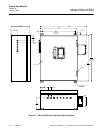
Model MicroCEM
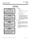
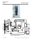
2-4 ELECTRICAL CONNECTIONS
NOTE
The enclosure is a NEMA 4. All entry loca-
tions must be sealed.
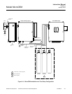
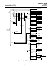
Connect all required signal cables to the con-
nections at the bottom of the MicroCEM. The
cable locations are indicated on the inside
bottom cover of the MicroCEM box. The ac-
tual electrical connections will be specified in
the Application Data package. All connections
are not necessary for every application.
Cable length for these signals should not ex-
ceed 3,000 feet (914 meters), to avoid exces-
sive capacitance and corresponding signal
distortion.
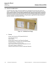
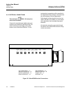
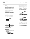
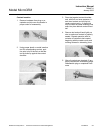
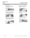
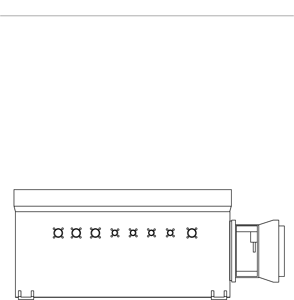
All electrical connections are made through
the bottom of the MicroCEM enclosure using
circular connectors.
AC POWER INPUT – J1 LAN INTERFACE – J5
ANALOG INTERFACE – J2 RS485 INTERFACE – J6
DIGITAL INTERFACE – J3 PHONE LINE – J7
RS232 INTERFACE - J4 ANTENNA – J8
Figure 2-5. MicroCEM Electrical Connections
AC POWER
INPUT
ANALOG
INTERFACE
DIGITAL
INTERFACE
RS232
INTERFACE
LAN
INTERFACE
RS485
INTERFACE
PHONE
LINE
ANTENNA