


Instruction Manual
748467-A
January 2002
Rosemount Analytical Inc. A Division of Emerson Process Management Description and Specifications 1-11
Model MicroCEM
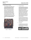
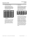
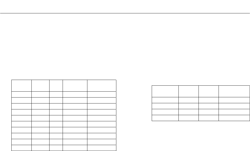
c. Programmable Input Ranges
A programmable gain amplifier, pro-
grammable unipolar/bipolar range, and
programmable 5V/10V full-scale range
combine to give the ADIO board a total of
10 different possible analog input ranges.
All range settings are controlled in soft-
ware for maximum flexibility.
Mode
Full-
scale
Gain
Input
Range
Resolution
Unipolar 10V 1 0-10V 0.153mV
Unipolar 5V 1 0-5V 0.076mV
Unipolar 5V 2 0-2.5V 0.038mV
Unipolar 5V 4 0-1.25V 0.019mV
Unipolar 5V 8 0-0.625V 0.0096mV
Bipolar 10V 1 ±10V 0.305mV
Bipolar 5V 1 ±5V 0.153mV
Bipolar 5V 2 ±2.5V 0.076mV
Bipolar 5V 4 ±1.25V 0.038mV
Bipolar 5V 8 ±0.625V 0.019mV
d. Enhanced Trigger and Sampling Con-
trol Signals
The ADIO board has an extra A/D trigger
and sample control signals in the design.
Seven auxiliary digital I/O lines on the
analog I/O connector provide a sam-
ple/hold output signal, A/D trigger in and
out lines (to enable synchronization of
multiple boards) and external A/D clock-
ing.
e. Analog Outputs
The ADIO board contains 4 12-bit analog
outputs with autocalibration capability. Up
to 5mA of output current per channel can
be drawn from all channels simultane-
ously. Both unipolar and bipolar output
ranges are supported with jumper con-
figuration. And on power up, all outputs
are reset to 0V automatically.
Mode
Full-
scale
Output
Range
Resolution
Unipolar 10V 0-10V 2.44mV
Unipolar 5V 0-5V 1.22mV
Bipolar 10V ±10V 4.88mV
Bipolar 5V ±5V 2.44mV
f. FIFO and 16-Bit Bus Interface
An on-board 1024-byte FIFO enables the
ADIO board to work with Windows 95 and
NT by dramatically reducing the interrupt
overhead. Each interrupt transfers 256 2-
byte samples, or half the buffer, so the
interrupt rate is 1/256 the sample rate.
FIFO operation can be disabled at slow
sample rates, so there is no lag time be-
tween sampling and data availability. The
16-bit interface further reduces software
overhead by enabling all 16 A/D bits to be
read in a single instruction, instead of re-
quiring 2 8-bit read operations. The net
result of this streamlined design is that the
ADIO board supports gap-free A/D sam-
pling at rates up to 200,000 samples per
second, twice as fast as our previous
boards.