


Instruction Manual
748467-A
January 2002
2-8 Installation Rosemount Analytical Inc. A Division of Emerson Process Management
Model MicroCEM
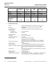
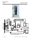
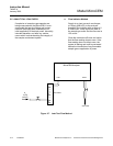
a. AC Power
Connect AC power through a 10A circuit
breaker that is to be located close to the
MicroCEM. The circuit breaker will pro-
vide over current protection as well as a
means of disconnecting the power.
Maximum power requirements will be 380
watts, with most applications requiring
less than this amount.
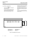
b. Circular Connector Assembly Instruc-
tions
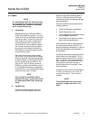
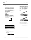
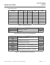
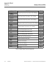
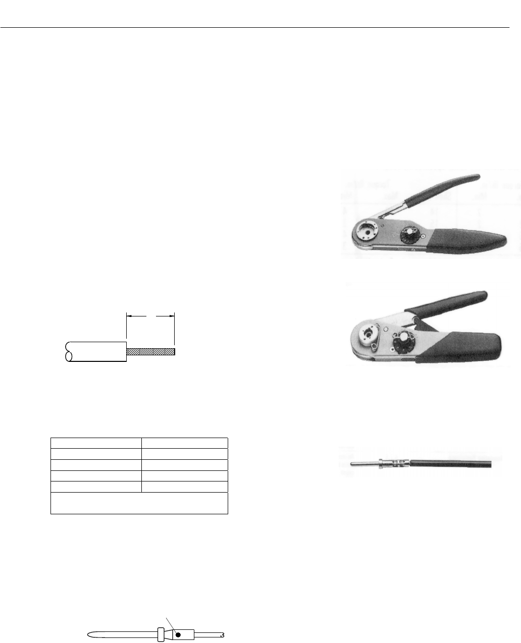
Wire Stripping
Strip insulation from end of wire to be
crimped. Do not cut or damage wire
strands. Refer to table for proper strip-
ping dimensions.
Wire Size Dim. A
22O or 22M* .125 (3.18)
20 .188 (4.77)
16 .188 (4.77)
12 .188 (4.77)
*Inactive. Not recommended for new
design, replacement only.
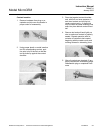
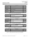
Contact Crimping
1. Insert stripped wire into contact crimp
pot. Wire must be visible through in-
spection hole.
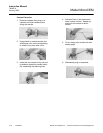
2. Using correct crimp tool and locator,
cycle the tool once to be sure the in-
dentors are open. Insert contact and
wire into locator. Squeeze tool han-
dles firmly and completely to insure
a proper crimp. The tool will not re-
lease unless the crimp indentors in
the tool head have been fully actu-
ated.
3. Release crimped contact and wire
from tool. Be certain the wire is visi-
ble through inspection hole in contact.
A
Visual Inspection Hole