


Instruction Manual
748467-A
January 2002
5-6 Maintenance and Service Rosemount Analytical Inc. A Division of Emerson Process Management
Model MicroCEM
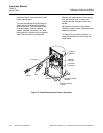
position of the O-ring and window in the
upper compartment.
The new photodiode should be slowly in-
serted into the housing while gradually
rotating the body. This allows the O-ring
to properly seat. Continue replacing
screws, washers, thermistors, etc., with
the thicker shim (washer) on the opposite
side of the socket from the thermistor.
Replace the lower section of the housing,
then the bottom cover, insulator and
bracket with the shoulder washers and
screws.
Re-tighten the screws in the Reaction
Chamber (upper section). Replace the top
cap and its screws.
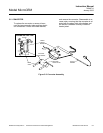
To reinstall in the Analyzer Module, re-
verse the procedure for removal as indi-
cated above.
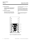
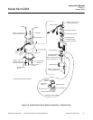
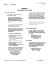
Figure 5-4. Chemiluminescense Detector Assembly
Photodiode
Ozone
Detector Mounting
Bracket
Photodiode Socket
Assembly
Thermistor
Assembly
Reaction
Chamber
Sapphire
Window
Exhaust
Sample