


M3099GX/GH OEM Manual 3-5
INTERFACE
Termination
All signals not defined as RESERVED, GROUND, or TERMPWR
shall be terminated at both ends of the cable. The Implementor may
choose one of the following two methods to terminate each end (see
ANSI SCSI-2 ANSI SCSI-2 5.4 Electrical description):
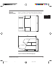
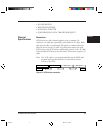
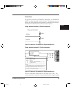
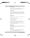
Single-ended alternative (a) [Passive terminator]
TERMINATOR POWER
220 Ω
330 Ω
–SIGNAL
GROUND
Figure 3.2 Alternative 1 termination for Single Ended Devices
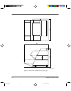
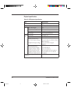
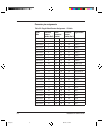
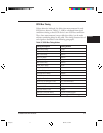
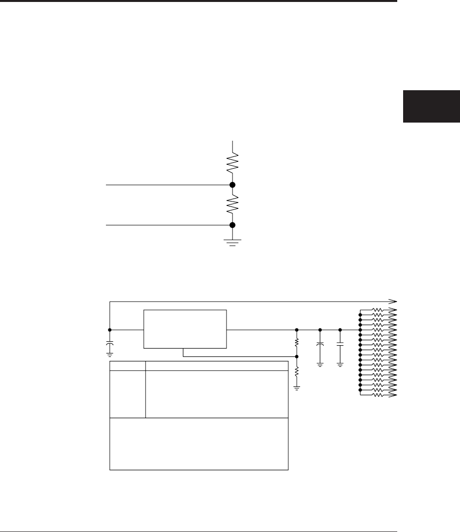
Single-ended alternative (b) [Active terminator]
Low dropout voltage regulater
Imax ≥ 600mA
Vout = 2.85V
(See Note 1)
Vin Vout
Vadj
R1
R2
C2 C3
+
R3
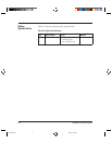
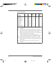
Component Description
R1
R2
R3-R20
C1
C2
C3
121 Ω, 1%, 0.25W
154 Ω, 1%, 0.25W
110 Ω, 1%
10 µF Alum.15V or 4.7 µF Tant. 15V
150 µF Alum.10V or 22 µF Tant. 10V (ESR at 120 Hz < 4)
0.1 µF Ceramic 25V
+
R20
NOTES
1 The voltage regulator shown is an adjustable type with Vref=1.25V.
R1 and R2 were selected to provide approximately 10mA Iquiescent.
The voltage regulator Vdropout shall be 1.25V or less at Imax.
2 Alternative values that provide lower performance at somewhat
lower cost use Vout 1%; R3−R20=100 Ω,2%
Figure 3.3 Alternative 2 termination for Single Ended Devices
The first termination method above is the same as in SCSI-1. The
second termination method is recommended for better signal quality.
#03.pm5 98.2.22, 1:31 PM5