


6 - 13
6-2-3 Test Equipment, Power Supply and Charts for Adjustment
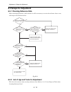
1) Color bar chart
2) 3100 K light box (maintenance is necessary)
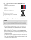
3) Backfocus chart
4) Color monitor (color TV with AV input jacks)
5) Oscilloscope
6) Vectorscope
7) Digital voltmeter
8) Frequency counter
9) DC power supply for DSP-R jig (5 V/1 A)
Information:
It is recommended that you use a vectorscope when
performing the chroma gain adjustment.
You can use an oscilloscope instead: Note, however, that
the adjustment accuracy will be lower.
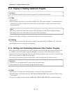
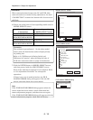
Fig. 6-2-2 Color Bar Chart
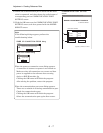
Fig. 6-2-3 Backfocus Chart
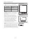
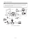
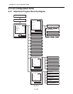
6-2-4 Connections for Adjustment
Connect the DVD video camera/recorder, jigs and test equipment as shown in the Fig. 6-2-4.
Prohibition:
Assemble the DVD video camera/recorder completely, and perform adjustment with only the
adjustment cover removed (see Fig. 6-2-4).
Do not attempt to perform any adjustment with the DVD video camera/recorder disassembled:
Doing so is very dangerous because the DVD video camera/recorder incorporates high-voltage
circuits and a laser emitter block.
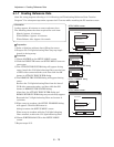
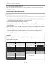
(1) Setting of light box
1) Use the same light box as when the reference data was created: Its color temperature and
illuminance are strictly controlled and free from flickering. If the setting of color box is not
appropriate, the adjustment program may not operate normally.
(2) Setting and disassembly of DVD video camera/recorder
1) Refer to “(1) Adjustment cover” in “5-3 Disassembly” for how to remove the adjustment cover.
2) Set the light box 30-50 cm away from DVD video camera/recorder, and eliminate any effects from
surrounding light, except where such designation is given.
3) Set the lens surface of DVD video camera/recorder in parallel with the surface of light box as far
as possible, and adjust the focus.
4) Use a small tripod to fix the DVD video camera/recorder, making certain it does not move during
creation of reference data.
5) Be sure to connect the video output of DVD video camera/recorder to the video input jack of color
monitor, which is usually terminated by 75 ohm: If the video output is not terminated by 75 ohm,
the video output value cannot be measured correctly.
Adjustment > Setups for Adjustment