


4 - 35
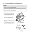
4-7-2 Disassembly/reassembly to enable service position
Prohibition
Be sure to disconnect the AC adapter/charger or battery from the DVD video camera/recorder.
The DVD video camera/recorder has a built-in laser emitter block. Never look into it: If Laser beam
strikes your eye, it could cause serious vision damage.
Information:
Numbers in diagrams are step numbers for setting procedure. Letters in [ ] show the types of
screw. Letters in brackets ( ) show the name of parts.
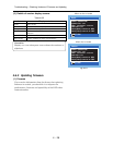
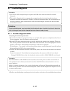
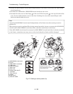
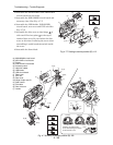
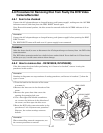
(1) Setting to service position (A)
Service position (A) is mainly used for trouble
diagnosis of the power supply system and the
system of disc cover/operation buttons on side
case-R. Perform trouble diagnosis using the
check points on MAN-H/MAN circuit board.
Remove the MAN-H/MAN circuit board in
advance, referring to “5. Disassembly and
Reassembly”.
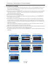
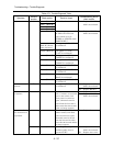
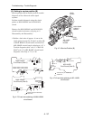
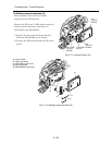
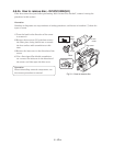
1) Solder a lead wire of approx. 10 cm to the
check points (except for IC pins) on side A of
MAN-H/MAN circuit board, referring to “4-7-
1 Trouble diagnosis table” and “C-1 MAN-H/
MAN” circuit board diagram. (See Fig. 4-7-2)
Fig. 4-7-1 Service Position (A)
LEAD
WIRES
LEAD
WIRES
MAN-H/MAN
CIRCUIT
BOARD
Fig. 4-7-2 Lead wire soldering
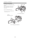
: Check point (TL: Test land)
: Lead wire
MAN-H/MAN
Ciruit Board (Side A)
TL0510
TL0513
TL0522
TL0515
TL0512
TL0517
TL2090 TL2085 TL2086 TL2082
TL2089 TL2091 TL2084 TL2095
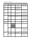
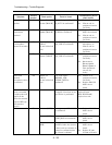
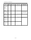
Troubleshooting > Trouble Diagnosis