


4 - 37
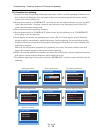
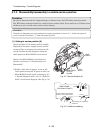
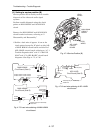
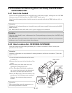
(2) Setting to service position (B)
Service position (B) is mainly used for trouble
diagnosis of the video and audio signal
systems.
Perform trouble diagnosis using the check
points on MAN-H/MAN and AEL-H/AEL
circuit
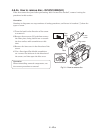
Remove the MAN-H/MAN and AEL-H/AEL
circuit boards in advance, referring to “5
Disassembly and Reassembly”.
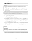
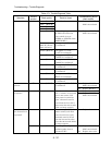
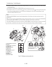
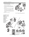
1) Solder a lead wire of approx. 10 cm to the
check points (except for IC pins) on side A/B
of MAN-H/MAN circuit board and side B of
AEL-H/AEL circuit board, referring to “4-7-1
Trouble diagnosis table” and “C-1 MAN-H/
MAN” and “C-2 AEL-H/AEL” circuit board
diagrams. (See Figs. 4-7-5, 4-7-6)
Fig. 4-7-4 Service Position (B)
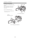
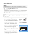
Fig. 4-7-5 Lead wire soldering of MAN-H/MAN
circuit board
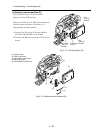
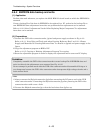
Fig. 4-7-6 Lead wire soldering of AEL-H/AEL
circuit board
MAN-H/MAN
CIRCUIT
BOARD
AEL-H/AEL
CIRCUIT
BOARD
LEAD
WIRES
LEAD
WIRES
TL0510
TL0513
TL0522
TL0515
TL0512
TL0517
TL2090 TL2085 TL2086 TL2082
TL2089 TL2091 TL2084 TL2095
TL0520(GND)
TL0521(GND)
TL0518
TL1547
TL1543
TL0511
TL0504
TL1535
TL1534
TL6006
TL6009
TL6010
: Check point (TL: Test land)
: Lead wire
MAN-H/MAN
Ciruit Board (Side A)
MAN-H/MAN
Ciruit Board (Side B)
TL7030
TL7028
TL3715
TL6101
TL6102 TL7041
TL3701(GND)
: Check point (TL: Test land)
: Lead wire
AEL-H/AEL
Ciruit Board (Side B)
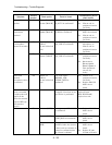
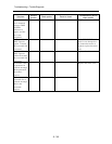
Troubleshooting > Trouble Diagnosis