


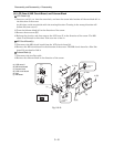
5 - 12
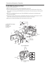
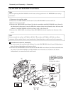
(1) Unlock
(2) Pull
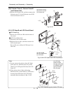
DZ-MV580E
DZ-MV550E
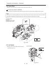
3) [G]
4)
5)
2) (c)
e
e
1)
(1)
(2)
3) [G]
3) [G]
(d)
(b)
(a)
(b)
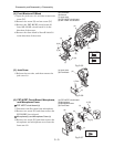
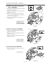
[G] M1.7x3 (Gold)
IC2006
IC4002
IC4106
IC2010
IC2009
IC2010
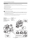
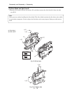
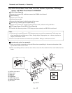
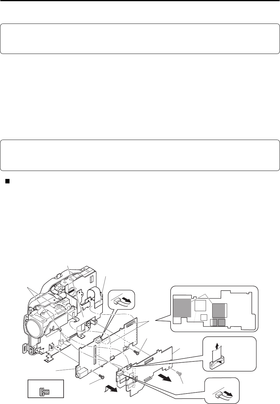
(15) AEL-H/AEL and MAN-H/MAN Circuit Boards
Note:
Before replacing the MAN-H/MAN circuit board, always perform “4-9-2 EEPROM data backup
and write”.
1) Disconnect the two flat cables.
2) Disconnect the DRF-H/DRF circuit board (c) from MAN-H/MAN circuit board (b).
3) Remove three screws [G].
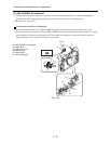
4) Remove the AEL-H/AEL circuit board (a) that is assembled with MAN-H/MAN circuit board in
the direction of the arrow: It may be difficult to remove these circuit boards, since the heat sink
rubbers (e) on MAN-H/MAN circuit board may stick to the frame (d).
5) Remove the AEL-H/AEL circuit board from MAN-H/MAN circuit board in the direction of the
arrow.
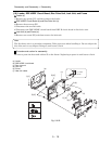
Note:
Do not scratch the surface of IC2009 or IC2010: The surfaces of IC2009 or IC2010 are silicon
substrate (silicon wafer) that is semi-conducting. Scratching them could cause fault in operation.
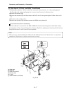
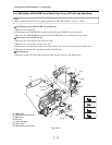
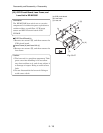
Procedure and caution for reassembly
1) Be sure to paste the two heat sink rubbers (e) on the MAN-H/MAN circuit board: Neglecting to
paste the heat sink rubber could cause a fault.
2) Connect the MAN-H/MAN circuit board and AEL-H/AEL circuit board, and then attach them to
the frame. If the MAN-H/MAN and AEL-H/AEL circuit boards are attached to the frame
independently, a connection fault could result.
Fig. 5-3-17
(a) AEL-H/AEL circuit board
(b) MAN-H/MAN circuit board
(c) DRF-H/DRF circuit board
(d) Frame
(e) Heat sink rubbers
Disassembly and Reassembly > Disassembly