


4 - 38
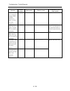
Troubleshooting > Trouble Diagnosis
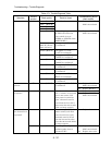
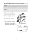
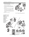
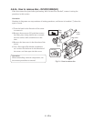
2) Assemble the MAN-H/MAN and AEL-H/AEL
circuit boards on the frame.
3) Assemble the SHE-H/SHE circuit board and
accessory shoe. (See Fig. 4-7-7)
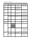
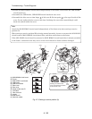
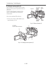
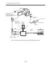
4) Assemble the USB holder, USB-H/USB
circuit board, rear cover and EVF unit.(See
Fig. 4-7-8)
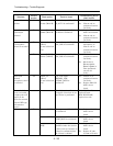
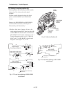
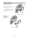
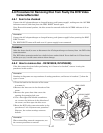
5) Assemble the disc cover so that hinge
1
of
side case-R fits into point
2
at the top of
inside of disc cover. Do not incline the disc
cover at this time: Inclining the cover when
assembling it could break the switch inside
the cover.
6) Assemble the front block.
Fig. 4-7-7 Setting to service position (B) -1/2-
Fig. 4-7-8 Setting to service position (B) -2/2-
(a) MAN-H/MAN circuit board
(b) AEL-H/AEL circuit board
(c) Frame
(d) SHE-H/SHE circuit board
(e) Accessory shoe
(f) Heat sink rubber
(g) USB holder
(h) USB circuit board
(i) Rear cover
(j) EVF unit
(k) Disc cover
(m)Hinge of side case-R
(n) Side case-R
(p) Flat cable
(q) Disc drive unit
(r) Loader
2) [G]
2)
2)
2) [G]
2) [G]
(c)
(e)
(b)
(f)
(a)
3) [G]
3) [H]
3) (d)
[G] M1.7x3 (Gold)
[H] M1.6x2 (Gold)
4) (g)
4) (h)
5)
4) [M]
4) [F]
4) [A]
(i)
4)
4) [A]
(j)
4)
4) [F]
(m)
(m)
(n)
2
(k)
(k)
5) (p)
(p)
5) [F]
5) [F]
(q)
(r)
(c)
(a)
1
(u)
6)
6) [B]
6) B]
Switch
Correct
Installing and inclined disc
cover could damage the switch
in side the disc cover.
Incorrect
Incorrect
Disc
cover
[A] M1.7×4 (Black)
[F] M1.6×2.5
(Black)
[M] M1.7×3 (Black)
[B] M1.7×4 (Silver)