


1 - 5
1-5 Notes When Using Service Manual
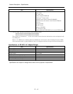
(1) Value units used in parts list
Certain symbols are indicated as shown below for value units of resistors, capacitors and coils in
parts list. When you read them, note the following regular indications:
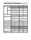
(2) Values in schematic diagrams
The values, dielectric strength (power capacitance) and tolerances of the resistors (excluding
variable resistors) and capacitors are indicated in the schematic diagrams using abbreviations.
Certain symbols are indicated for value units: When you read them note the regular indications in
tables below:
[Resistors] [Capacitors]
[Coils]
Indication in list Regular indication
KOHM
.........................................
k
UF
................................................
µF
PF
................................................
pF
UH
...............................................
µH
MH
..............................................
mH
Parts
Resistor
Capacitor
Coil
Item
Value
Tolerance
Power
capacitance
Indication
No indication
..............................
K
..................................................
k
M
.................................................
M
No indication
..............................
±5%
(All tolerances other than ±5% are
indicated in schematic diagrams)
No indication
..............................
1/8W
(1/16 W for leadless resistors with no
indication)
All capacitances other than the above
are indicated in schematic diagrams.
Item
Value
Dielectric
strength
Indication
No indication
..............................
µF
P
..................................................
pF
No indication
..............................
50V
(All dielectric strengths other than
50 V are indicated in schematic
diagrams)
Item
Value
Indication
µ
...................................................
µH
m
..................................................
mH
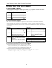
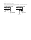
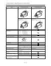
(3) Identifications of sides A/B in circuit board diagrams
1) Board with a pattern on one side and parts on both sides:
Side A: Shows discrete parts, viewed from the pattern side.
Side B: Shows leadless parts, viewed from the pattern side.
2) Board with patterns on both sides and parts on both sides:
Side A: Shows parts and patterns which can be seen when the case is opened.
Side B: Shows parts and the pattern on the back of side A.
Safety Precaution for Repair > Notes When Using Service Manual