


6 - 14
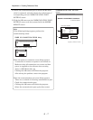
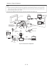
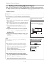
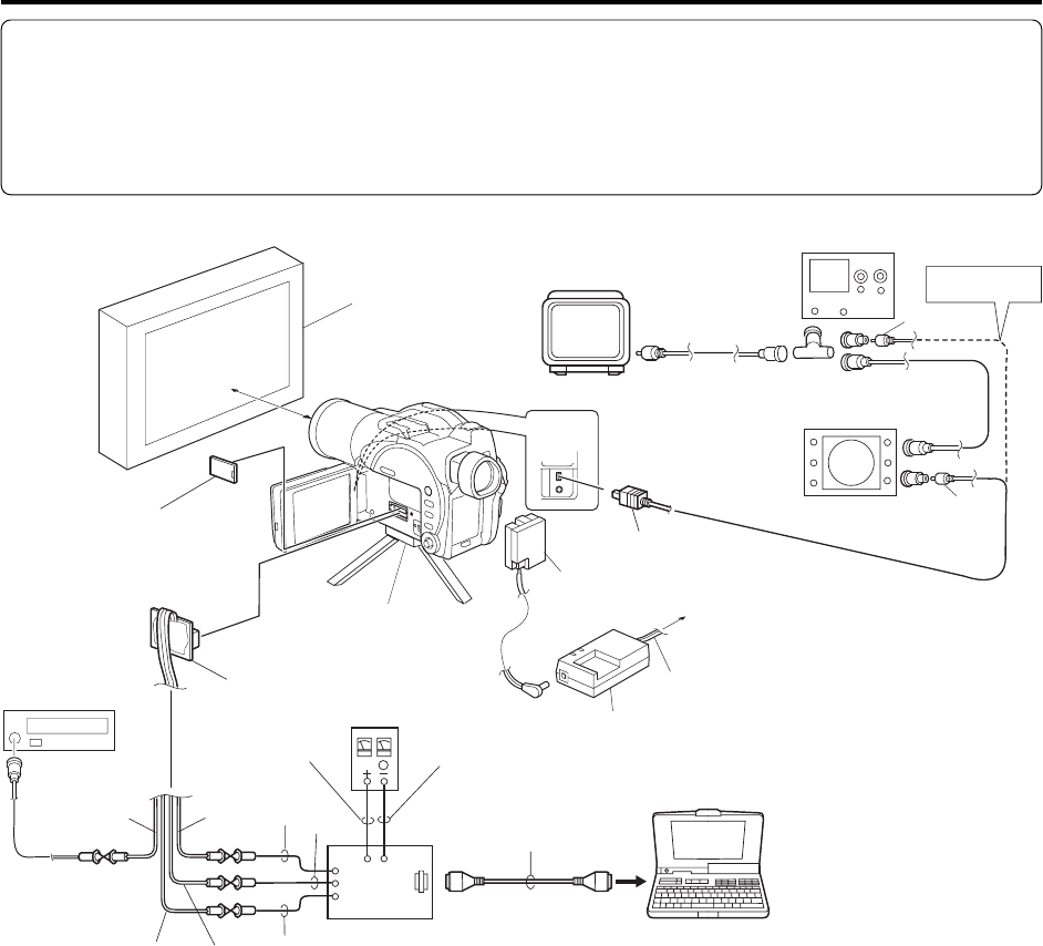
Fig. 6-2-4 Connections for Adjustment
DSP-R JIG
CH1
CH2
WHT
RD
(PIN 18)
YEL
BLK
BLK
RED
PC
DZ-ACS1
GND
(PIN 16)
SD
(PIN 20)
30-50cm
LCD-HDD
(PIN 9)
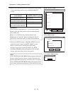
FREQUENCY
COUNTER
VECTOR SCOPE
OSCILLOSCOPE
Nothing VECTOR
SCOPE
REMOVE THE
ADJUSTMENT COVER
[Refer to "(1) Adjustment cover"
in "5-3 Disassembly".]
LIGHT BOX
TRIPOD
DC
POWER
SUPPLY
(5V/1A)
SKYLARK
CONNECTION
JIG
RS-232C
CABLE
POWER CABLE
To AC OUTLET
DC POWER
CORD
FRONT
SECTION
YEL
To
VIDEO IN
AV/S INPUT/OUTPUT
CABLE
COLOR
MONITOR
To INPUT
To OUTPUT
TEL
Adjustment > Setups for Adjustment
Note:
1) Always connect the Skylark connection jig before connecting the DC power cord to the DVD
video camera/recorder: Connecting the Skylark connection jig after powering the DVD video
camera/recorder could cause a fault.
2) Connect the Skylark connection jig so that the lead wires from jig face up.