


6 - 41
6-4-11 EVF
Note:
1) Perform EVF only after replacing IC3701 and its peripheral components, MAN-H/MAN circuit
board or EVF unit, or executing “Initial Data Write”.
2) Neither light box nor chart is needed for EVF adjustment.
Before performing any adjustments for EVF, be sure to shift the DVD video camera/recorder to the
test mode using the procedure below, and then display the EVF ADJUSTMENT MENU.
Adjustment > Adjustment Procedure
Procedure:
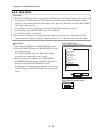
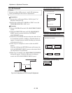
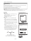
1) Choose EVF on the ADJUST MENU screen.
2) Click the EXECUTE button on ADJUST MENU screen
to shift the DVD video camera/recorder to the test mode.
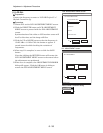
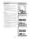
The progress status can be confirmed using the
PROGRESS STATUS dialog.
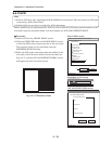
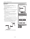
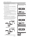
3) When the DVD video camera/recorder has shifted to the
test mode, the viewfinder screen will be black and white
(see Fig. 6-4-12), and the EVF ADJUSTMENT MENU
will appear on the PC monitor screen.
ADJUST MENU screen
EVF ADJUSTMENT MENU screen
MANUAL ADJUSTMENT PROGRAM for SERVICE STATION
MODEL NAME:
××××
DATA INITIALIZE
EXECUTE
RETURN
CONNECTION
ADJUST MENU
SAMPLING PULSE
AUTO IRIS CONTROL
MATRIX
CHROMA GAIN
AUTO FUCUS
SPOT NOISE
LCD
EVF
VIDEO LEVEL
BURST LEVEL
2
1
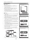
EVF ADJUSTMENT INITIALIZE
PLEASE WAIT A MOMENT
MANUAL ADJUSTMENT PROGRAM for SERVICE STATION
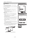
EVF ADJUSTMENT MENU
PLL
EXECUTE
RETURN
CONNECTION
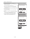
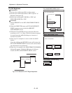
EVF ADJUSTMENT MENU
WHITE BALANCE
BRIGHT
CONTRAST
Fig. 6-4-12 EVF Screen
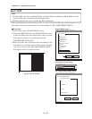
PROGRESS STATUS dialog