


4 - 43
Troubleshooting > Special Functions
4-9-2 EEPROM data backup and write
(1) Application
Perform this work whenever you replace the MAN-H/MAN circuit board on which the EEPROM is
mounted.
Create a backup file of the data in EEPROM to be replaced in a PC, and write the backup file to
new EEPROM: Some adjustment items that are performed after replacement can be omitted.
Refer to “6-3-2 List of Adjustments Needed After Replacing Major Components” for adjustment
items that can be omitted.
(2) Preparations
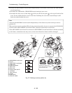
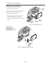
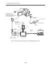
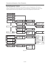
1) Connect the DVD video camera/recorder, jig/tool and power supply as shown in Fig. 4-9-3.
Refer to “6-1-1 List of Jigs and Tools used when Creating Reference Data” and “6-1-2 Power
Supply and Materials for Creating Reference Data” for details on jig/tool and power supply in the
figure.
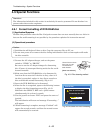
2) Copy the adjustment program to HDD of PC.
Refer to “6-1-5 Copying or Deleting Adjustment Program” for copying.
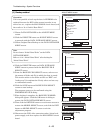
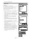
3) Start the adjustment program in order to display the adjustment menu screen on PC display.
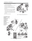
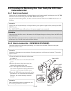
Prohibition:
Completely assemble the DVD video camera/recorder; create backup file of EEPROM data and
write it with only the adjustment cover removed (see Fig. 4-9-3).
Do not attempt to perform work with the DVD video camera/recorder disassembled: Doing so is
very dangerous because the DVD video camera/recorder incorporates high-voltage circuits and a
laser emitter block.
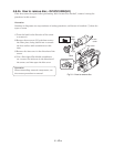
Note:
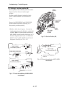
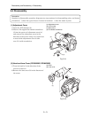
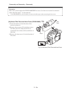
1) Always connect the Skylark connection jig before connecting the DC power cord to the DVD
video camera/recorder: Connecting the Skylark connection jig after powering the DVD video
camera/recorder could cause a fault.
2) Connect the Skylark connection jig so that the lead wires from jig face up.