


4 - 36
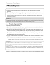
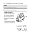
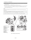
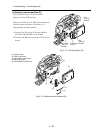
2) Attach the MAN-H/MAN circuit board independently to the frame, and connect the DRF-H/DRF
circuit board to it.
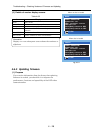
3) Assemble the USB holder, USB-H/USB circuit board and rear cover.
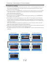
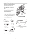
4) Assemble the disc cover so that hinge
1
of side case-R fits into point
2
at the top of inside of disc
cover. Do not incline the disc cover at this time: Inclining the cover when assembling it could
break the switch inside the cover.
Note:
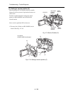
Attach the MAN-H/MAN circuit board independently of the frame only when setting to service
position (A).
When setting to service position (B) or during normal assembly, be sure to connect the AEL-H/AEL
circuit board to MAN-H/MAN circuit board first, and then attach them to the frame.
If the AEL-H/AEL circuit board is connected to MAN-H/MAN circuit board that is already attached
to the frame, connection error may occur, or the circuit boards or frame could be damaged.
(a) MAN-H/MAN circuit board
(b) Frame
(c) DRF-H/DRF circuit board
(d) USB holder
(e) USB circuit board
(f) Rear cover
(g) Disc cover
(h) Hinge of side case-R
(i) Flat cable
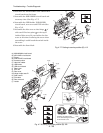
(j) Disc drive unit
(k) Loader
(m)Side case-R
(n) Heat sink rubber
Fig. 4-7-3 Setting to service position (A)
Troubleshooting > Trouble Diagnosis
3) (d)
3) (e)
2) (c)
2)
2) [G]
2) [G]
3) [F]
3) [M]
3) [F]
3) [A]
3)
4)
2
4) (i)
4) [F]
4) [F]
1
Correct Incorrect Incorrect
(b)
(n)
(f)
(h)
(g)
(a)
(a)
(m)
(j)
(i)
(k)
(h)
(g)
(b)
Disc
cover
Switch
Installing and inclined disc
cover could damage the switch
in side the disc cover.
[G] M1.7x3 (Gold)
[A] M1.7x4 (Black)
[F] M1.6x2.5 (Black)
[M] M1.7x3 (Black)