


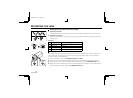
CONNECTIONS
Before making any connection, make sure all the peripheral devices
are turned off.
Multiple units are connected in series using twisted-pair cables (bridge
connection). To set the addresses and make other fine adjustments,
please refer to page 57.
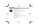
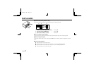
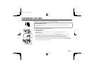
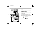
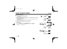
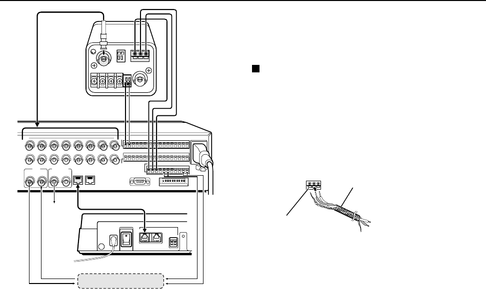
RS-485 terminal connections
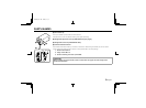
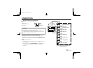
Connect a shielded twisted-pair cable (AWG22) from signal A to
signal A, and from signal B to signal B of the RS485 control terminal
of each of the devices.
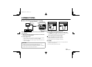
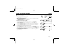
• Connection to a VCR
Make the connection between the RS485 (A, B, G) terminal on this
unit and the VCR RS485 A and B terminals and the C terminal.
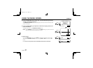
• Connection to a multiplexer
Make the connection between the RS485 (A, B, G) terminal on this
unit and the multiplexer control terminals (A, B, C).
Monitor
Timelapse VCR
CAMERA IN
terminal
RS485
control
terminal
System controller
Multiplexer
12345678910111213141516C
910111213141516
CABC
AL
C
R1 R2
C
SW
C
VCR
12AB
RS485
MONITOR
IN OUT
ALARM IN
CONTROL
SENSOR ALARM
OUT
12V DC IN
POWER
ON
RS485
GND
A
B
B
G
A
B
ALARM input
terminal
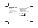
Shielded twisted-pair cable
To A signal
To B signal
Ground
GBA
Push in to insert cable
L53R4/US GB 1999, 12, 7
English 11