


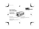
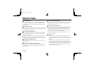
PARTS NAMES
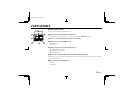
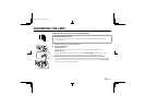
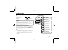
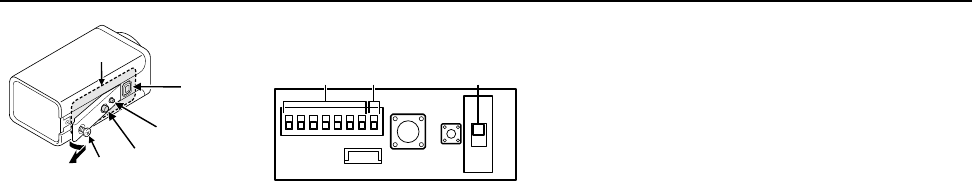
8 Camera setup section (under the cover)
To access the controls, loosen the cover fixing screw A, then remove the cover.
a Address setting switch (RS485 ADDRESS) . . . See page 57
b Terminater switch (TERMINATE) . . . . . . . . . . See page 57
c Auto iris lens switch (A. I. LENS) . . . . . . . . . . See page 7
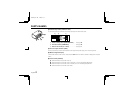
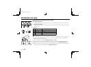
9 Lens iris output connector (LENS)
This 4-pin connector is used to send the DC control signal and power supply to an auto-iris type lens.
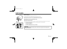
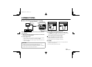
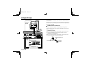
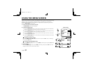
F Menu setting button (SET)
Connect the camera to the monitor, then press the SET button for about 3 seconds to display the on-screen
menu.
G Cursor button (CURSOR)
j: Press this button to move the cursor up.
c: Press this button to move the cursor to the right, or to turn the settings ON/OFF etc.
d: Press this button to move the cursor to the left, or to turn the settings ON/OFF etc.
l: Press this button to move the cursor down.
8
9
A
F
G
a b c
L53R4/US GB 1999, 12, 7
English 5