


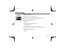
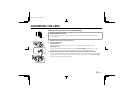
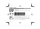
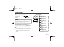
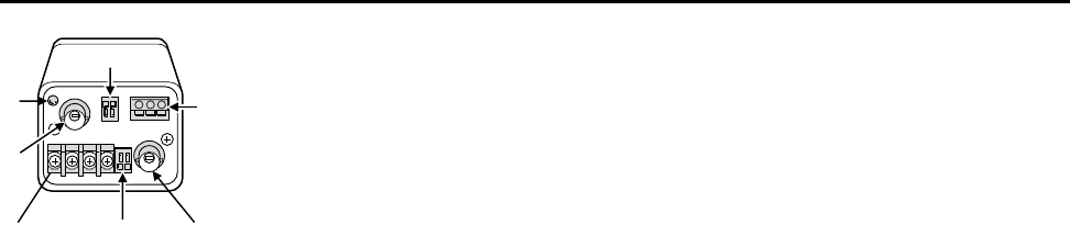
PARTS NAMES
1 Power indicator (POWER)
Comes on when the power to the camera is on.
2 Video output connector (VIDEO OUT: BNC type)
Connect this connector to a device such as a VCR or monitor with a VIDEO IN connector.
3 24 V AC or 12 V DC input terminal (AC 24 V, DC 12 V, GND)
4 Remote control terminal (REMOTE, C, R)
R: Remote input
C: Common
5 RS-485 control push-lock terminal (RS485, G, B, A)
A: Twisted-pair cable terminal
B: Twisted-pair cable terminal
G: Ground terminal
6 External sync composite video signal input connector (VBS IN: BNC type)
Connect to this connector the synchronizing signal output from a synchronizing signal device or the composite
signal of a video distributor.
7 Alarm output terminal (ALARM, C, A)
A: Alarm
C: Common
1
6
2
3
4
7
5
L53R4/US GB 1999, 12, 7
4 English