


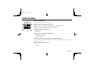
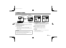
CONNECTIONS
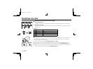
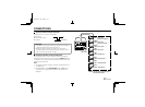
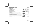
About the Alarm output terminal
Connect this unit to a VCR or a multiplexer.
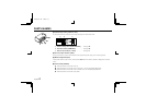
Alarm output
A: Alarm signal output
C: Common
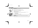
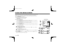
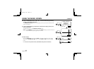
CAUTION:
• The digital processing of the settings may disturb the image for
a few seconds after the camera is turned on.
• While the menus are being set, noise sent on the lines by
peripheral devices may cause the settings to change. In such a
case, turn the power off then on again.
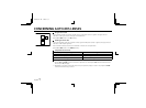
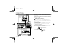
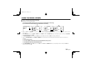
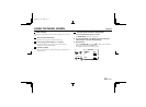
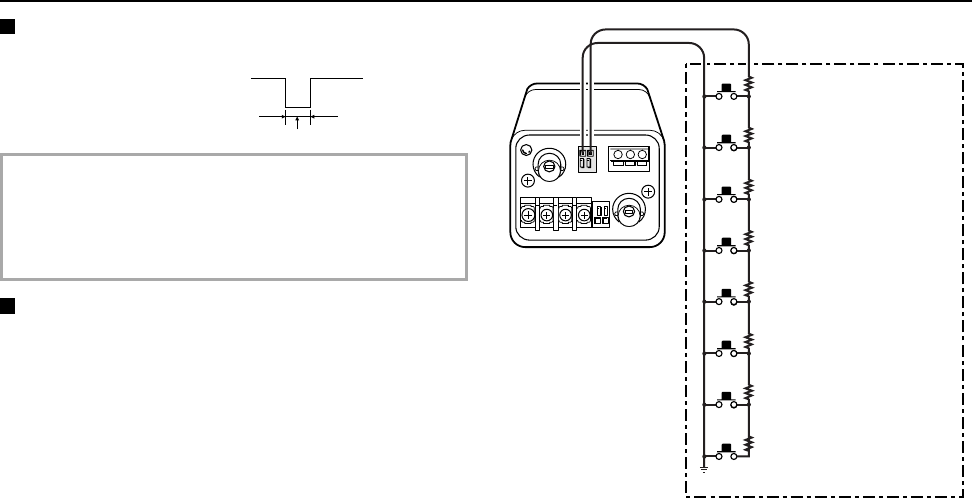
Remote controller circuit connections
Use the layout above to make a remote controller and make the
connections to the remote input pins (C, R) of the REMOTE terminal
as indicated. This will permit remote controlled operation of this unit.
(make contact LOW input)
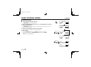
Note:
• The maximum length of cable for remote controlled operation is
6 m (AWG 24).
• If the ZOOM item in the OPTION MENU is set to ON, remote
controlled zoom is possible even while the menu screens are
displayed.
Alarm active
About 500 msec.
5 V
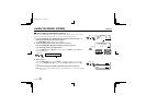
SW 1
SW 2
SW 3
SW 4
SW 5
SW 6
SW 7
SW 8
1.1kΩ
0.68kΩ
0.91kΩ
1.2kΩ
1.8kΩ
2.7kΩ
3.9kΩ
9.1kΩ
: Zoom (wide)
: Zoom (tele)
: Panning (left)
: Panning (right)
: Tilting (upward)
: Tilting (down)
SW: switch
: Electric PTZ
(pan-tilt-zoom) preset
: Electric PTZ
(pan-tilt-zoom) OFF
CR
*Preset: will return to the zoom (pan,
tilt) center position.
*
L53R4/US GB 1999, 12, 7
12 English