


2
Chapter 2 Locations and Functions of Parts and Controls2-8
When CH-1 of the AUDIO IN switch is set to REAR:
The signal input to the MIC IN connector is recorded in channel 3.
MUTE: Does not record any input signals in channels 3 and 4.
For more information, refer to the Maintenance Manual.
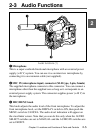
With the HDCA-901 (not supplied) connected to the camcorder, you can
record separate sounds in audio channels 3 and 4.
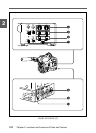
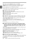
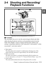
7 CUE IN (cue track input) switch
This switch selects the input signal to be recorded on the cue track.
CH-1: CH-1 input signal
MIX: Mixed input signals of CH-1 and CH-2
CH-2: CH-2 input signal
8 AUDIO OUT (audio output) connector (XLR type, 5-pin, male)
This connector outputs the audio signals recorded to audio channels 1
and 2 or audio channels 3 and 4.
The PB AUDIO CH item on the VTR SETUP page of the
MAINTENANCE menu allows you to select the audio signal to be
played back.
For more information, refer to the Maintenance Manual.
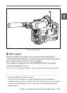
9 AUDIO IN CH-1/CH-2 (audio channel 1 and channel 2 input)
connectors (XLR type, 3-pin, female) and LINE/MIC/+48 V ON
(line input/microphone input/external power supply +48 V ON)
switches
These are audio input connectors for channels 1 and 2 to which you can
connect audio equipment or a microphone.
The LINE/MIC/+48V ON switches select the audio source of the audio
input signals connected to each of these connectors.
LINE: Line input audio equipment
MIC: Microphone with an internal power supply
+48V ON: Microphone with an external power supply system
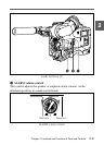
0 DC OUT (DC power output) connector
This connector supplies power for a WRR-28M/860 UHF Portable Tuner
(not supplied). Do not connect any equipment other than the UHF
portable tuner.